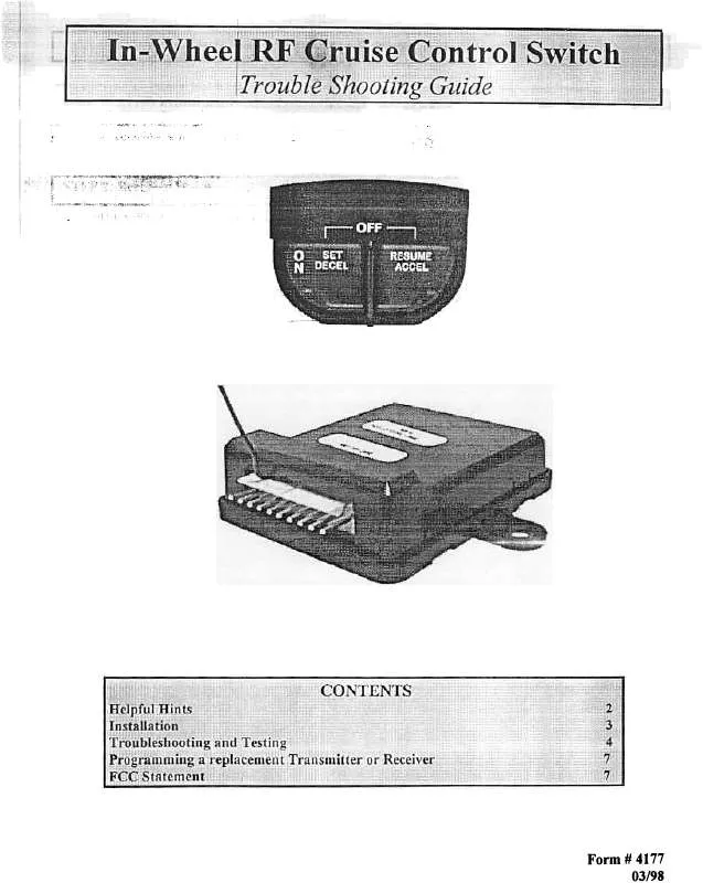
Detailed instructions for use are in the User's Guide.
[. . . ] Receiver Module Installation:
to vehicle, 9wners , , ,
, manual
for
2
Remove existing Cruise Control Switch, if one exists. Refer tp Ifelpful Hint #2 to when disconnecting 4 pin connector. Choose a location under the driver's side dash to mount the receiver module. This location should be chosen such that interfacing to the existing cruise control harness does not cause stress on the wiring harness. [. . . ] The diagram below illustrates the wire locations, colors, and lunctions on the wirillg harness entering lIl(; cruise colllrol module.
lRlvlBlYIBRIGRIDGIBLUI Figure J: Wire Locations from left to right entering the cruise control Abbreviation R Color Red
Violet Black
module
Function Control Switch
I
Abbreviation BR
Color Brown
Function Ignition Power
Power
v B
Brake
Light Ground
G round
OR DO
BLU
~ Dark Green BLUE
VSS
Signal
Set/Decel
y
Ycllo\y
Rcsumc/Accel
Tach Signal
Page
4
,
-, . . ;" '. 0'-
each function listed with the vehicle and cruise control If results are observed contrary to the indicated desired , fail codes for debugging instructions.
;t. ;, ~f"r. ;c;' , -, c
1 . , A-l I T~~T INo A-2 . FUNCTION Power
OFF
Ignition , Ignition
"OFF' "ON",
I 0. 0 (zcro)VDC at all wires 12VI)C on BROWN wire
r
then press
, t'
" '1'"' " ~
"'SET' "SET'
button, and
then press both "RESUME" I b11!fnnc; together
12VDC on RED wire before pressing both buttons, I O (zero)VDC on RED wire after pressing both buttons.
Ignition A-4
. ~N"
12VDC on "BROWN" wire I 12VDC on "RED" wire I 12VDC on "VIOLET'
12VDC WIre on "DARK GREEN"
Ignition "ON" Push Brake Pedal
wire
A-5
SET/DECEL
Ignition "ON" Push "SET' Button
12VDC on "YELLOW"
\\, irf'
!3
1, A-7
4. 5VDC to 0. 0 (zero)VDC on "ORA Y" wire, 3-4 times in 10 feet
I (Volt meter) Ground meter) System I (Ohm
A-8
, -, , '
, \ , ~ 0;
Ignition
"OFF'
Continuity to Ground on "BLACK" wire
I!, ;;, "";, :;;", "~;;;;;;", ;;i;;;", ,
B-1
CC"" , ""
. iB. . l
Re lace remote Checki : '
conti"olled ,
ctuiseswjtchtfariSffijtterandreceiver!" , b. 'c "
8-3
8-4 B-5 B-6
g
Table I: Instructions
for diagnostic fail codes
l
Page 5
~
Mechllnical Tests
Veri(v the cruise cable and linkage is properly installed by visually inspecting all related parts of the throttle connection Verify that the cruise control cable is free to operate from obstruction or resistance. Verify that all brackets are secured properly and not damaged. Turn the Cl1lise Control Switch to tile OFF position 2. Turn the ignition switch to the OFF position 1. Turn the ignition switch to the ON position . vithout starting the engine, hold the RESUME/ACCEL down while you turn the Cl1lise Control Switch to the ON position. ) 4. The Diagnostics LED should be off at this time. Tcstin2 thc Cl1lise Control Switch, Brake S, vitchWirin2, and Vehiclc Specd Sensor (VSS) Signal:
button
IF
NOT
Press and release SET/COAST button. LED should light each time button is pressed and go out when it is released. I IF YES
Lheck steps to enternlg dlagtlostlcs mode 1Indtry again Cht:t:k Progranuning Switch #7: 01, 'F- Nonnallv OPEN switch
IF NOT
r to Actuator Assembly, if diagnostic commands are
IF YES
J Check Cruise Control Switch
IF NOT
IF NOT Lli", , ;'; "", ps to ~llt~rillg diiigllOStic Illod;; and try again Check Programming Switch #10: ON Vehicle speed sensor (ECM) I r set incorrectly, reset and re-enter diagnostic mode Some vehicles need to be ptlShed more Ihm1tl1ree (3) feet I !
IF
YES
Page
6
;;"', ""f
c"-
M~,
f
~
at the factory or receiver are replaced. Install the new transmitter or receiver as described in the manual attached. Use Volt/Ohmmeter to verify the steps you are about to make. Connect the Volt/Ohmmeter to the Jrd pin from the left (next to Orange wire) on the lO-pin connector of the interface harness. The Volt/Ohmmeter should read (+5 starting the engine. 5: Turn the ignition power on, without volts ). 6 Locate the Orange wire with the Tee- Tap on the interface harness. Using the jumper harness, momentarily ground the Orange wire. The Volt/Ohmmeter should read (0. 0 volts). 9, Using the jumper harness, momentarily ground the Orange wire again. 10; The Volt/Ohmmeter should read (+5 volts). [. . . ] Do not use Cruise Control on slippery roads or in heavy traffic.
f
w ARNING When conneetmg this system to the vehicle, ensure that you follow this instruction manual and connect only to spccifi~ wires. Failure to do this may causethe cruise control switch to work improperly, cause electrical or engine failure. and may result in damage to the vehicle and/or injury to the occupants. We must depend on your skill and good judgment as you install this system. [. . . ]


