User manual DRAKE DIGITAL DMM 806
Lastmanuals offers a socially driven service of sharing, storing and searching manuals related to use of hardware and software : user guide, owner's manual, quick start guide, technical datasheets... DON'T FORGET : ALWAYS READ THE USER GUIDE BEFORE BUYING !!!
If this document matches the user guide, instructions manual or user manual, feature sets, schematics you are looking for, download it now. Lastmanuals provides you a fast and easy access to the user manual DRAKE DIGITAL DMM 806. We hope that this DRAKE DIGITAL DMM 806 user guide will be useful to you.
Lastmanuals help download the user guide DRAKE DIGITAL DMM 806.
Manual abstract: user guide DRAKE DIGITAL DMM 806
Detailed instructions for use are in the User's Guide.
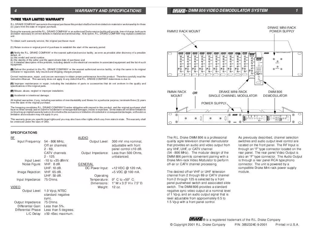
[. . . ] DRAKE COMPANY may replace a defective unit. To obtain such warranty service, the original purchaser must: (1) Retain invoice or original proof of purchase to establish the start of the warranty period. DRAKE COMPANY or the nearest authorized service facility, as soon as possible after discovery of a possible defect, of: (a) the model and serial number, (b) the identity of the seller and the approximate date of purchase; and (c) A detailed description of the problem, including details on the electrical connection to associated equipment and the list of such equipment. DRAKE COMPANY or the nearest authorized service facility, or ship the same in its original container or equivalent, fully insured and shipping charges prepaid. [. . . ] Drake DMM 806 is a professional quality agile television channel demodulator that provides an audio and video output from any VHF, UHF, or CATV channel (54 - 806 MHz). The modular design of the DMM 806 permits convenient pairing with a Drake Mini-rack Video Modulator to perform off-air or CATV channel processing. The desired off-air VHF or UHF television channel from 2 through 69 or CATV channel from 2 through 125 is selected by a front panel pushwheel switch and associated slide switch. The DMM 806 provides a standard negative sync video output at a nominal level of 1 Vp-p, and an audio output signal that is level adjustable from approximately 0. 5 to 1. 5 Vp-p with a front panel control. As previously described, channel selection switches and audio output level control are located on the front panel. The RF Input is through an "F" type connector located on the rear panel. The rear panel Video Output is also an "F" type connector. The Audio Output is through a rear panel RCA type phono connector. The unit is powered by a compatible Drake Mini-rack power supply module.
Output Impedance:
GENERAL DC Power Input: Operating Temperature: Dimensions: Weight:
+12 VDC @ 120 mA, +5 VDC @ 100 mA. 12 oz.
® is a registered trademark of the R. L. Drake Company © Copyright 2001 R. L. Drake Company P/N: 3852324E-9-2001 Printed in U. S. A.
CATV
AUDIO
PWR
0
+100
CH
2 FRONT PANEL DESCRIPTION
F1
DMM 806
PWR
REAR PANEL DESCRIPTION
R1
VIDEO OUT
INSTALLATION
CONNECTIONS and CONTROLS All connections to and from the DMM 806 are made through the rear panel. Figure 3 illustrates the use of the DMM 806 as an offair channel processor. For this purpose, the feed from a television antenna is connected via a 75 Ohm coaxial cable to the RF IN connector of the DMM 806. The front panel switches are set for "OFF-AIR" and the received TV channel number is set for 02 through 69 as required. The VIDEO OUT and AUDIO OUT signals are connected to the VIDEO IN and AUDIO IN connectors respectively of an adjacently located Video Modulator, such as a Drake Mini-rack Video Modulator, operating on the desired cable TV
3
channel. Alternatively, cable TV channels can be processed by connecting the 75 Ohm coaxial cable of a CATV feed to the DMM 806 RF IN connector and setting the front panel switches for "CATV" or "CATV +100" and the received cable channel number 02 through 125 as required. Additional channels can be processed by adding combinations of DMM 806 units with Drake Mini-rack Video Modulator units. [. . . ] R2 - AUDIO OUTPUT Connector This is the unbalanced, audio output which is adjustable with the front panel AUDIO control over a range of approximately ± 10 dB from the nominal output level of 300 mV rms. NOTE: An internal jumper defeats the audio de-emphasis for stereo capability, if required. R3 - DC INPUT Connector This 3-pin connector (Male) accepts the appropriate mating DC power cable. R4 - RF INPUT Connector This is the 75 Ohm input to the demodulator circuits from an off-air television receiving antenna or from a CATV cable input.
AC POWER CORD
TV ANTENNA OR CATV FEED
DMM 806
DC POWER CABLE
CH
CH
Audio - Flat RF COMBINER SYSTEM OUT
2
OFF AIR CATV
5
CATV
2
OFF AIR CATV
5
CATV
Audio De-emphasis (factory setting) INTERNAL JUMPER Front Panel
Figure 3 Illustration of Channel Processing using DMM 806 and a Drake Mini-rack Video Modulator.
+100
+100
®
R. L. [. . . ]
DISCLAIMER TO DOWNLOAD THE USER GUIDE DRAKE DIGITAL DMM 806 Lastmanuals offers a socially driven service of sharing, storing and searching manuals related to use of hardware and software : user guide, owner's manual, quick start guide, technical datasheets...manual DRAKE DIGITAL DMM 806


