User manual HONEYWELL S2024-2POS
Lastmanuals offers a socially driven service of sharing, storing and searching manuals related to use of hardware and software : user guide, owner's manual, quick start guide, technical datasheets... DON'T FORGET : ALWAYS READ THE USER GUIDE BEFORE BUYING !!!
If this document matches the user guide, instructions manual or user manual, feature sets, schematics you are looking for, download it now. Lastmanuals provides you a fast and easy access to the user manual HONEYWELL S2024-2POS. We hope that this HONEYWELL S2024-2POS user guide will be useful to you.
Lastmanuals help download the user guide HONEYWELL S2024-2POS.
Manual abstract: user guide HONEYWELL S2024-2POS
Detailed instructions for use are in the User's Guide.
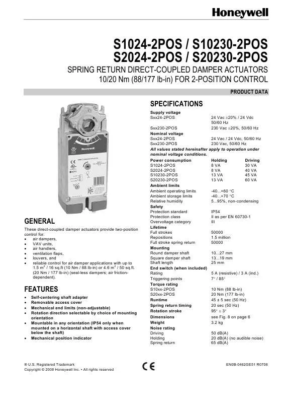
[. . . ] (20 Nm / 177 lb-in) (seal-less dampers; air frictiondependent).
FEATURES
· · · · · · Self-centering shaft adapter Removable access cover Mechanical end limits (non-adjustable) Rotation direction selectable by choice of mounting orientation Mountable in any orientation (IP54 only when mounted on a horizontal shaft with access cover below the shaft) Mechanical position indicator
® U. S. Registered Trademark Copyright © 2008 Honeywell Inc. · All rights reserved
EN0B-0462GE51 R0708
SmartAct S1024-2POS / S10230-2POS, S2024-2POS / S20230-2POS
MODELS
order number S1024-2POS S1024-2POS-SW2 S10230-2POS S10230-2POS-SW2 S2024-2POS S2024-2POS-SW2 S20230-2POS S20230-2POS-SW2 supply voltage 24 Vac 24 Vac 230 Vac 230 Vac 24 Vac 24 Vac 230 Vac 230 Vac end switches -2 -2 -2 -2 power consumption 30 VA (driving) / 8 VA (holding) 10 Nm (88 lb-in) 45 VA (driving) / 13 VA (holding) 40 VA (driving) / 8 VA (holding) 20 Nm (177 lb-in) 60 VA (driving) / 13 VA (holding) torque
Product Identification System
N = non-spring return S = spring return 10 = 10 Nm (88 lb-in) 20 = 20 Nm (177 lb-in) 010 = modulating + floating 24 = 24 V 230 = 230 V
SmartAct S 2 0 2 3 0 X
Fig. Product Identification System
OPERATION / FUNCTIONS
Contents of Package
1 2 3 4 5 6 Self-centering shaft adapter Retainer clip Rotational angle scales (0. . . 90° / 90. . . 0°) Mechanical end limits (non-adjustable) Hex wrench for manual adjustment Access cover
CCW to close (failsafe position) CW to open
CW to close (failsafe position) CCW to open
Rotary Movement
The actuators are designed to open a damper by driving the damper shaft in either a clockwise or counterclockwise direction. [. . . ] Internal end switch triggering points
Mechanical Stroke Limit Reduction
For applications requiring a span of less than 95°, a simple adjustment can be made. When the rotational mounting of the shaft coupling is changed, the actuator drives less than the full 95° stroke. The stroke is adjustable in 5° increments. Once adjusted, the actuator drives until the shaft coupling reaches the mechanical stop (part of the housing). The stop causes the motor to discontinue driving, and the shaft coupling drives no farther. When the actuator returns, it stops at the fail-safe position. To set the fail-safe position, proceed as follows: 1. Remove the retainer clip from the shaft coupling and set it aside for later use. Remove the shaft coupling from the actuator. Rotate the coupling to the desired fail-safe position, aligning it based on the stroke labeling. EXAMPLE: Setting the shaft coupling to an approx. fail-safe position of 35° (as indicated on the housing) limits the stroke to 60° (see Fig. 5).
Releasing the Manual Positioning
To release the manual positioning with no power present, proceed as follows: 1. Turn the key ¼ of a turn in the direction indicated on the cover. Remove the key without engaging the gear train lock pin. The spring will return the actuator to the failsafe position. NOTE: Once power is restored, the actuator will return to normal automated control.
95°
4. Install the shaft coupling at this position. [. . . ] TWO-POSITION CONTROL
END SWITCHES
NOTE: Internal end switches S1 and S4 must be connected to the same power source. S10230-2POS / S20230-2POS
CW 1 100% 2 3 4 TERMINAL STRIP 1 5 Connect via safety isolating transformer!TWO-POSITION CONTROL
230 Vac~ 230 V
S10230-2POS-SW2
S1 black
230 Vac~ 230 V TERMINAL STRIP 1
CW 1 100% 2 3 4 5
S1 S2 S3 S4 S5 S6
S2 black S3 black S4 gray S5 gray S6 gray
END SWITCHES
Connect via safety isolating transformer!TWO-POSITION CONTROL
END SWITCHES
NOTE: Internal end switches S1 and S4 must be connected to the same power source.
5
EN0B-0462GE51 R0708
SmartAct S1024-2POS / S10230-2POS, S2024-2POS / S20230-2POS
DIMENSIONS
100 50 50 64 (min. ) 76 (min. [. . . ]
DISCLAIMER TO DOWNLOAD THE USER GUIDE HONEYWELL S2024-2POS Lastmanuals offers a socially driven service of sharing, storing and searching manuals related to use of hardware and software : user guide, owner's manual, quick start guide, technical datasheets...manual HONEYWELL S2024-2POS


