User manual HUSQVARNA W 3213
Lastmanuals offers a socially driven service of sharing, storing and searching manuals related to use of hardware and software : user guide, owner's manual, quick start guide, technical datasheets... DON'T FORGET : ALWAYS READ THE USER GUIDE BEFORE BUYING !!!
If this document matches the user guide, instructions manual or user manual, feature sets, schematics you are looking for, download it now. Lastmanuals provides you a fast and easy access to the user manual HUSQVARNA W 3213. We hope that this HUSQVARNA W 3213 user guide will be useful to you.
Lastmanuals help download the user guide HUSQVARNA W 3213.
Manual abstract: user guide HUSQVARNA W 3213
Detailed instructions for use are in the User's Guide.
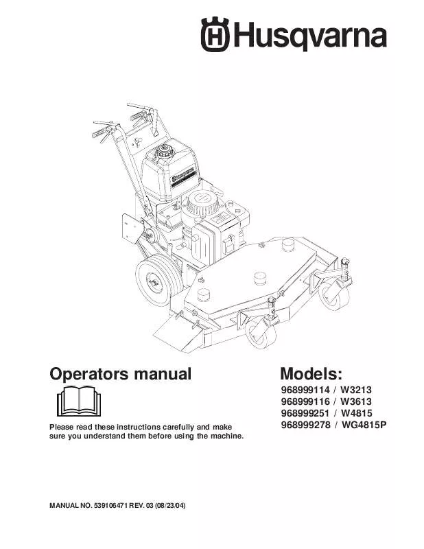
[. . . ] Operators manual
Please read these instructions carefully and make sure you understand them before using the machine.
Models:
968999114 968999116 968999251 968999278 / / / / W3213 W3613 W4815 WG4815P
MANUAL NO. 03 (08/23/04)
TABLE OF CONTENTS
SAFETY : Training Preparation Operation Maintenance EQUIPTMENT SETUP AND ADJUSTMENTS : Front casters Axle adjustment Cutting height chart Brake adjustment Operator presence switches Belt adjustments OPERATING INSTRUCTIONS : Emergency stopping Normal stopping Pre-start Operating instructions SERVICE : Interlock system Cutting deck Cutter housing Belt replacement Winter storage Maintenance chart
©2004 Husqvarna. Printed U. S. A.
2
INTRODUCTION This manual has been prepared for the operators of the HUSQVARNA 32", 36" commercial mowers. Read, understand, and follow the safety and operating instructions. [. . . ] Firmly pull back on the handles until the tires slide to seat the wheel drive belts into the pulleys. Measure the clearance between the bottom of the traction lever rod and the bottom of the thumb latch slot. It should be between 3/16" to 1/4", but not exceeding 1/4". LEVER OPERATOR PRESENCE SWITCH ADJUSTMENT The operator presence switches can be adjusted by loosening the screws on the side of the O. P. lever linkage and sliding the switch up or down. switch should have a 1/32" to 1/16" gap between the plunger and the bottom side of the control panel when operator presence levers are released. BLADE SWITCH ADJUSTMENT The blade engagement switch can be adjusted by loosening the screws on the flange under the control panel and moving the switch in or out. The blade switch should be adjusted so the plunger is fully depressed when the engagement lever is fully disengaged. BLADE ENGAGEMENT LEVER The blade engagement lever needs to be adjusted so the lever does not come in contact with control panel when the lever is in the off position. To adjust, remove the clevis pin from the yoke and adjust by turning the yoke. The clevis pin connects the blade engagement lever to the yoke, and the yoke is connected to the blade engagement rod that runs to the bellcrank on the rear deck.
32" & 36" MODEL
102036 1/2" 1/8" CLEARANCE 103462 TRANSMISSION BELT 1/2" 102036
48" MODEL 1/4" CLEARANCE 103462 TRANSMISSION BELT
ENGINE PULLEY 103463 1/8" CLEARANCE TRANSMISSION IDLER PULLEY
ENGINE PULLEY 103462 1/8" CLEARANCE TRANSMISSION IDLER PULLEY
Figure 4
AUXILARY BELT ADJUSTMENT ROD TURNBUCKLE
Figure 5
1/4"
IDLER PIVOT POINT
ENGAGEMENT IDLER ASSEMBLY
Figure 6
9
Operating Instructions
BEFORE OPERATING Be thoroughly familiar with all controls and how to use them before operating the mower. Know beforehand how to stop the engine, drive wheels, and mower blades in preparation for possible emergency. EMERGENCY STOP Pull both traction levers firmly against handle grips and hold them securely in place. Use thumb latches to lock both traction levers in neutral position, then stop engine by pulling throttle control back to the off position. LEVER PRE-START CHECKLIST Make the following checks and perform the services as required before each start up. If required make cutting height adjustments and drive linkage adjustments. Check tires for proper inflation (front caster tire pressure to be 50 lbs max. Check guards, deflectors, and covers to make sure all are in place and secure. Check blade belts for wear and correct tension if worn or damaged, replace with original part. Clean interior and exterior surfaces of the cutting deck and clean engine of any accumulation of dirt or debris. Keep engine air intake clear at all times. Check engine oil add if needed (do not overfill) refer to engine manual for oil specs. [. . . ] Loosen the engine bolts with belt guides and rotate them away from the engine pulley. Belt guides can be seen in figure 4 on page 9. Loosen the belt guides located around the pulleys on the front deck. Belt guides are 5/16" bolts and must be loosened to remove the belt. [. . . ]
DISCLAIMER TO DOWNLOAD THE USER GUIDE HUSQVARNA W 3213 Lastmanuals offers a socially driven service of sharing, storing and searching manuals related to use of hardware and software : user guide, owner's manual, quick start guide, technical datasheets...manual HUSQVARNA W 3213


