User manual KB ELECTRONICS KBRC-240D
Lastmanuals offers a socially driven service of sharing, storing and searching manuals related to use of hardware and software : user guide, owner's manual, quick start guide, technical datasheets... DON'T FORGET : ALWAYS READ THE USER GUIDE BEFORE BUYING !!!
If this document matches the user guide, instructions manual or user manual, feature sets, schematics you are looking for, download it now. Lastmanuals provides you a fast and easy access to the user manual KB ELECTRONICS KBRC-240D. We hope that this KB ELECTRONICS KBRC-240D user guide will be useful to you.
Lastmanuals help download the user guide KB ELECTRONICS KBRC-240D.
Manual abstract: user guide KB ELECTRONICS KBRC-240D
Detailed instructions for use are in the User's Guide.
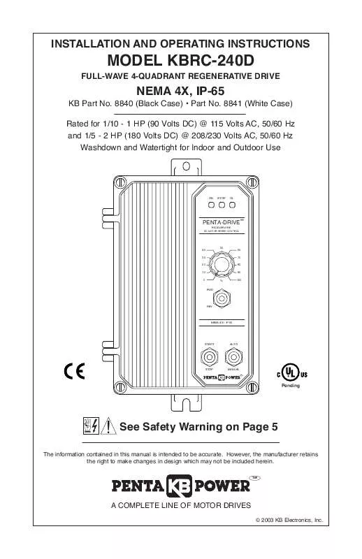
[. . . ] INSTALLATION AND OPERATING INSTRUCTIONS
MODEL KBRC-240D
FULL-WAVE 4-QUADRANT REGENERATIVE DRIVE
NEMA 4X, IP-65
KB Part No. 8841 (White Case) Rated for 1/10 - 1 HP (90 Volts DC) @ 115 Volts AC, 50/60 Hz and 1/5 - 2 HP (180 Volts DC) @ 208/230 Volts AC, 50/60 Hz Washdown and Watertight for Indoor and Outdoor Use
ON
STOP
OL
TM
PENTA-DRIVE
REGENERATIVE DC MOTOR SPEED CONTROL
40 30 20 10 0
50
60 70 80 90
% FWD
100
REV
NEMA-4X / IP-65
START
AUTO
STOP
MANUAL
TM
Pending
!
See Safety Warning on Page 5
The information contained in this manual is intended to be accurate. However, the manufacturer retains the right to make changes in design which may not be included herein.
TM
A COMPLETE LINE OF MOTOR DRIVES
© 2003 KB Electronics, Inc.
TABLE OF CONTENTS Section i. Page
Simplified Operating Instructions . [. . . ] Note: The tach-generator input is designed for 7 Volt or 50 Volt per 1000 RPM tach-generators used with 1800 RPM motors. For a tach-generator other than 7 Volt or 50 Volt per 1000 RPM or for motors other than 1800 RPM, an external 1/2 Watt resistor (RT) must be installed. Install RT in series with the tach-generator, as shown in Figure 16. Jumper J3 must be set to the "7V" position. FIGURE 15 DC TACH-GENERATOR CONNECTION
TT+ RELAY
FIGURE 16 DC TACH-GENERATOR CONNECTION WITH ADDITION OF RT
TT+ RELAY
TB3
TB3
G -
DC TACH-GENERATOR
RT
G -
The value of RT in can be calculated using the following formula: RT = (4. 37 X VT X S) - 55000 Where VT is the tach-generator voltage (in Volts per 1000 RPM) and S is the base speed of the motor (in RPM). Example: Suppose you have a 20 Volt per 1000 RPM tach-generator with a 3600 RPM motor. RT = (4. 37 X 20 X 3600) - 55000 = 259640 Choose the closest 1/2 Watt resistor value, which is 240000 (240k) or 270000 (270k). Readjustment of the MAX trimpot may be necessary to achieve the desired maximum output voltage. SETTING SELECTABLE JUMPERS The KBRC-240D has selectable jumpers which must be set before the control can be used. See Figure 1, on page 7, for location of jumpers. FIGURE 17 AC LINE INPUT VOLTAGE SELECTION A. AC Line Input Voltage Control Set for 208/230 Volt AC Line Input Control Set for 115 Volt AC Line Input (Factory Setting) Selection (J1 and J2) J1 Set for 208/230 J2 Set for 208/230 J1 Set for 115 J2 Set for 115 Jumpers J1 Volt AC Line Volt AC Line Volt AC Line Volt Ac Line and J2 are J1 J1 J2 both factory J2 230V 115V 115V 230V 230V 115V 115V 230V set to the "230V" position for 208/230 Volt AC line input. For 115 Volt AC line FIGURE 18 MOTOR VOLTAGE input, set both Jumpers J1 and J2 to the SELECTION "115V" position. Motor Voltage Selection (J3) Jumper J3 is factory set to the "A180" position for 180 Volt motors. For 90 Volt motors, set Jumper J3 to the "A90" position. See Figure 18.
J3 Set for 180 Volt Motor (Factory Setting) J3 Set for 90 Volt Motor
A90 A180 T7 T50
A90 A180 T7 T50 J3
14
+ DC TACH-GENERATOR
+
J3
Note: If Jumper J3 is set to the "T7" or "T50" position, a tach-generator must be wired to Terminal Block TB3. If a tach- generator is not used, Jumper J3 must be in either the "A180" or "A90" position. If jumper J3 is in the "T7" or "T50" position, and a tach-generator is not used, the motor will accelerate to full speed and the Main Speed Potentiometer will not control speed. DC Tach-Generator Voltage Selection (J3) Jumper J3 is factory set to the "A180" position for 180 Volt motors. When connecting a tach-generator to Terminal Block TB3, set Jumper J3 to the corresponding voltage of the tach-generator being used. Note: If using a tach-generator other than 7V or 50V per 1000 RPM, see Section IIIK, on page 13. Motor Current Selection (J4) Jumper J4 is factory set to the "10A" position for 10 Amp motors. [. . . ] If the OL LED remains illuminated during normal control operation, a fault condition may exist. Possible causes for this condition are as follows. If the motor is a shunt wound type, the field may be open or not receiving proper voltage. Check position of CL trimpot and setting of jumper J4. [. . . ]
DISCLAIMER TO DOWNLOAD THE USER GUIDE KB ELECTRONICS KBRC-240D Lastmanuals offers a socially driven service of sharing, storing and searching manuals related to use of hardware and software : user guide, owner's manual, quick start guide, technical datasheets...manual KB ELECTRONICS KBRC-240D


