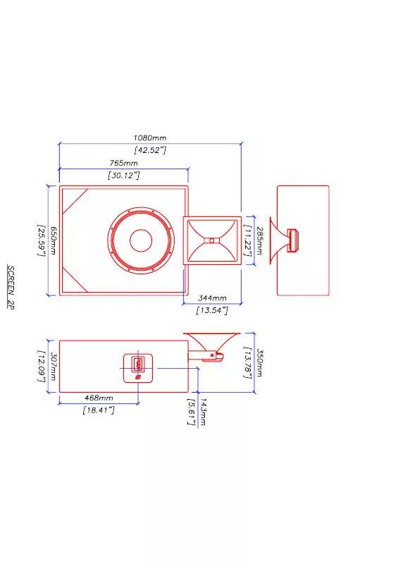
User manual MARTIN AUDIO SCREEN2P SCHEMATICS
Lastmanuals offers a socially driven service of sharing, storing and searching manuals related to use of hardware and software : user guide, owner's manual, quick start guide, technical datasheets... DON'T FORGET : ALWAYS READ THE USER GUIDE BEFORE BUYING !!!
If this document matches the user guide, instructions manual or user manual, feature sets, schematics you are looking for, download it now. Lastmanuals provides you a fast and easy access to the user manual MARTIN AUDIO SCREEN2P. We hope that this MARTIN AUDIO SCREEN2P user guide will be useful to you.
Lastmanuals help download the user guide MARTIN AUDIO SCREEN2P.
Manual abstract: user guide MARTIN AUDIO SCREEN2PSCHEMATICS
Detailed instructions for use are in the User's Guide.
[. . . ] Refer servicing to qualified service personnel.
Safeguards
Electrical energy can perform many useful functions. This unit has been engineered and manufactured to assure your personal safety. Improper use can result in potential electrical shock or fire hazards. In order not to defeat the safeguards, observe the following instructions for its installation, use and servicing.
Approvals
*
* MA18K pending This equipment has been tested and found to comply by Competent Body (Directive 89/336/EEC-EMC) pursuant to the product family standard for audio professional use: EN 55103-1, EN 55103-2 EN61000-3- 2 & EN 61000-3-3. [. . . ] Your 9. 6K, 12K & 18K amplifier uses a forced-air cooling system to maintain a low, even operating temperature. Drawn by an internal fan, air enters through the slots in the front panel and courses over and through components.
All material © 2007. Subject to change without notice.
The 9. 6K, 12K & 18K series amplifiers feature an "intelligent" variable-speed DC fan which is controlled by heat sink temperature sensing circuits: the fan speed will increase only when the temperature of either heat sink requires it, which keeps fan noise to a minimum and helps cut dust accumulation inside. Under extreme thermal load, the fan will force a very large volume of air through the heat sinks. If either heat sink gets too hot, its sensing circuit will reduce the output power. If the amplifier overheats, another sensing circuit shuts down its circuit to cut off power until it cools to a safe temperature. The exhaust cooling air is forced out through the rear of the chassis (see below), so make sure there is enough space around the sides of the amplifier to allow the air to escape. If it is rack mounted, make sure the exhaust air can flow without resistance. If you are using a rack with closed backs, there must be at least one standard rack space of opening in the front of the rack for every four amplifiers. Amplifiers may be stacked directly on top of each other (no space needed between units), starting from the bottom of the rack. 1. 3 Operating Precautions Make sure the AC mains voltage is correct and is the same as that printed on the rear of the amplifier. For each device the 1+ and 2+ pins of speakon connector are connected inside and have to be considered the positive output of the channel; the 1- and 2- pins of speakon connector are connected inside and have to be considered the negative output of the channel. Note: Channel B is internally polarity reversed. The first green LED at the bottom side of the LED bar indicates, when lighted, the presence of input audio signal above -60 dBV on the corresponding channel. From the second green LED to the yellow one, each LED represents 3dB. The green LEDs will be lit during normal working. If the level of the audio signal reach the channel output capability, a red LED will be triggered. The LED bars have diagnostic function also; a flashing yellow LED indicates a critic range of temperature (from 80°C to 85°C) of the power devices on the corresponding channel, if this LED is lit continuously, the temperature is above 85°C. A continuously lit red LED indicates that the corresponding channel is in protection.
All material © 2007. Subject to change without notice.
The fourth line of the screen shows the functions of the buttons below. The "lock" function is activated if the corresponding button is pressed more than 1 second; in this case all the other buttons are locked. The same operation unlocks these buttons (unlock code is required - see section 2. 3. 18 for more details). [. . . ] 2. 3. 17 LCD contrast In this screen you can set the contrast of the LCD display by pushing the +/- buttons (see figure 2. 3. 10)
2. 3. 18 Set unlock code In this screen you can insert the numeric key to unlock the settings. The same screen appears when the "unlock" button in the main screen is pressed. There is a universal key to unlock the settings. This is 270156.
2. 3. 19 Service This function is factory reserved.
All material © 2007. [. . . ]
DISCLAIMER TO DOWNLOAD THE USER GUIDE MARTIN AUDIO SCREEN2P Lastmanuals offers a socially driven service of sharing, storing and searching manuals related to use of hardware and software : user guide, owner's manual, quick start guide, technical datasheets...manual MARTIN AUDIO SCREEN2P


