User manual MAXTOR SAVVIO 15K.2 SAS
Lastmanuals offers a socially driven service of sharing, storing and searching manuals related to use of hardware and software : user guide, owner's manual, quick start guide, technical datasheets... DON'T FORGET : ALWAYS READ THE USER GUIDE BEFORE BUYING !!!
If this document matches the user guide, instructions manual or user manual, feature sets, schematics you are looking for, download it now. Lastmanuals provides you a fast and easy access to the user manual MAXTOR SAVVIO 15K.2 SAS. We hope that this MAXTOR SAVVIO 15K.2 SAS user guide will be useful to you.
Lastmanuals help download the user guide MAXTOR SAVVIO 15K.2 SAS.
You may also download the following manuals related to this product:
Manual abstract: user guide MAXTOR SAVVIO 15K.2 SAS
Detailed instructions for use are in the User's Guide.
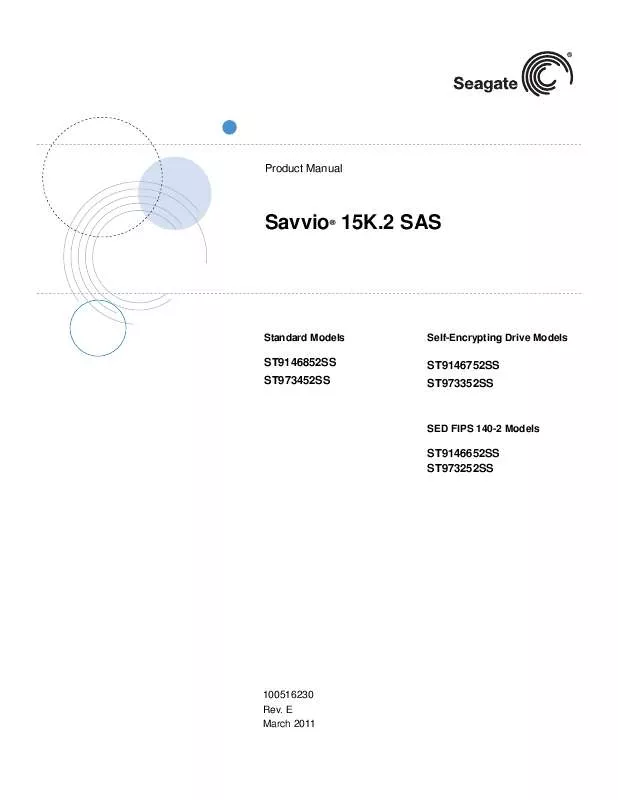
[. . . ] Product Manual
Savvio 15K. 2 SAS
®
Standard Models
Self-Encrypting Drive Models
ST9146852SS ST973452SS
ST9146752SS ST973352SS
SED FIPS 140-2 Models
ST9146652SS ST973252SS
100516230 Rev. E March 2011
© 2011, Seagate Technology LLC All rights reserved. E March 2011 Seagate, Seagate Technology and the Wave logo are registered trademarks of Seagate Technology LLC in the United States and/or other countries. Savvio and SeaTools are either trademarks or registered trademarks of Seagate Technology LLC or one of its affiliated companies in the United States and/or other countries. [. . . ] During idle, the drive heads are relocated every 60 seconds to a random location within the band from three-quarters to maximum track.
Savvio 15K. 2 SAS Product Manual, Rev. E
23
General DC power requirement notes. Minimum current loading for each supply voltage is not less than 1. 7% of the maximum operating current shown. The +5V and +12V supplies should employ separate ground returns. Where power is provided to multiple drives from a common supply, careful consideration for individual drive power requirements should be noted. Where multiple units are powered on simultaneously, the peak starting current must be available to each device. Parameters, other than spindle start, are measured after a 10-minute warm up. 7. 2. 1 Conducted noise immunity
Noise is specified as a periodic and random distribution of frequencies covering a band from DC to 10 MHz. Maximum allowed noise values given below are peak-to-peak measurements and apply at the drive power connector.
+5V +12V = = 250 mV pp from 100 Hz to 20 MHz. 250 mV pp from 20 KHz to 5 MHz.
7. 2. 2
Power sequencing
The drive does not require power sequencing. The drive protects against inadvertent writing during power-up and down.
24
Savvio 15K. 2 SAS Product Manual, Rev. E
7. 2. 3 Current profiles The +12V and +5V current profiles for the Savvio 15K. 2 SAS drives are shown below.
Figure 1. Current profile for 146GB models.
Savvio 15K. 2 SAS Product Manual, Rev. E
25
Figure 2.
Current profile for 73GB models
Note: All times and currents are typical. See Tables 2 and 3 for maximum current requirements.
26
Savvio 15K. 2 SAS Product Manual, Rev. E
7. 3
Power dissipation
146GB models in 6. 0 Gbit operation Typical power dissipation under idle conditions in 6. 0 Gb operation is 4. 37 watts (14. 91 BTUs per hour). To obtain operating power for typical random read operations, refer to the following I/O rate curve (see Figure 3). Locate the typical I/O rate for a drive in your system on the horizontal axis and read the corresponding +5 volt current, +12 volt current, and total watts on the vertical axis. To calculate BTUs per hour, multiply watts by 3. 4123.
Figure 3.
146GB models (6. 0 Gbit) DC current and power vs. input/output operations per second
146GB models in 3. 0 Gbit operation Typical power dissipation under idle conditions in 3. 0 Gbit operation is 4. 32 watts (14. 74 BTUs per hour). To obtain operating power for typical random read operations, refer to the following I/O rate curve (see Figure 3). Locate the typical I/O rate for a drive in your system on the horizontal axis and read the corresponding +5 volt current, +12 volt current, and total watts on the vertical axis. [. . . ] See Table 13 for signal type and signal name information. 12. 5. 1 Ready LED Out
The Ready LED Out signal is driven by the drive as indicated in Table 14. Table 14: Ready LED Out conditions
LED status 0 Off On On Off 1 Off On Off On
Normal command activity
Ready LED Meaning bit mode page 19h
Spun down and no activity Spun down and activity (command executing) Spun up and no activity Spun up and activity (command executing) Spinning up or down Format in progress, each cylinder change
Blinks steadily (50% on and 50% off, 0. 5 seconds on and off for 0. 5 seconds) Toggles on/off
The Ready LED Out signal is designed to pull down the cathode of an LED. The anode is attached to the proper +3. 3 volt supply through an appropriate current limiting resistor. [. . . ]
DISCLAIMER TO DOWNLOAD THE USER GUIDE MAXTOR SAVVIO 15K.2 SAS Lastmanuals offers a socially driven service of sharing, storing and searching manuals related to use of hardware and software : user guide, owner's manual, quick start guide, technical datasheets...manual MAXTOR SAVVIO 15K.2 SAS


 MAXTOR SAVVIO 15K.2 SAS REV D (1236 ko)
 MAXTOR SAVVIO 15K.2 SAS REV C 7-2009 (1262 ko)
