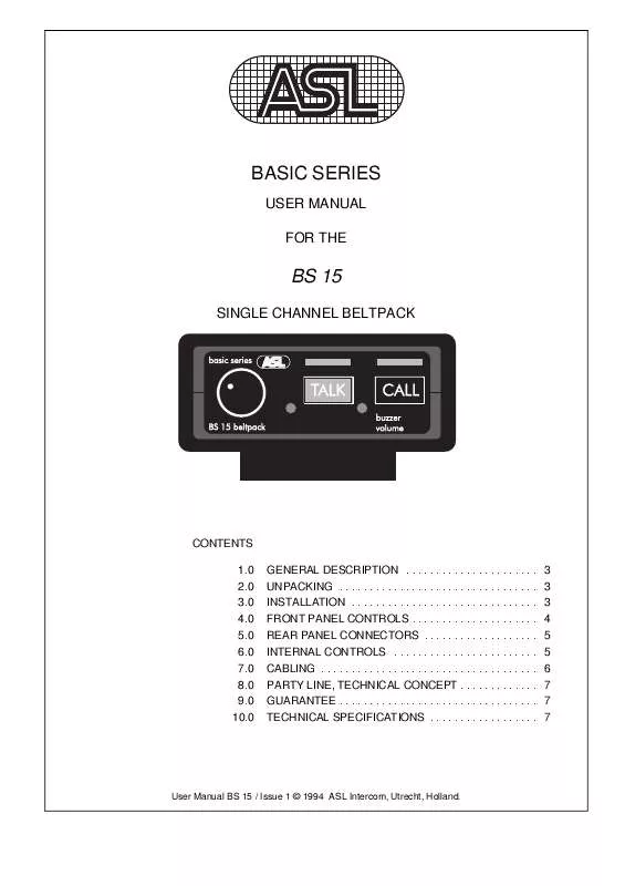
User manual ASL INTERCOM BS 15
Lastmanuals offers a socially driven service of sharing, storing and searching manuals related to use of hardware and software : user guide, owner's manual, quick start guide, technical datasheets... DON'T FORGET : ALWAYS READ THE USER GUIDE BEFORE BUYING !!!
If this document matches the user guide, instructions manual or user manual, feature sets, schematics you are looking for, download it now. Lastmanuals provides you a fast and easy access to the user manual ASL INTERCOM BS 15. We hope that this ASL INTERCOM BS 15 user guide will be useful to you.
Lastmanuals help download the user guide ASL INTERCOM BS 15.
You may also download the following manuals related to this product:
Manual abstract: user guide ASL INTERCOM BS 15
Detailed instructions for use are in the User's Guide.
[. . . ] Please also refer to the guarantee section of this manual.
The shipping carton contains the parts listed below: * * The BS 15 User manual
If any are missing, contact your dealer.
3. 0
INSTALLATION
This BS 15 will form part of an existing or new intercom system, and connection to it is straightforward. There are no separate power connections, or batteries to install, as the necessary DC voltages are derived from the intercom master station or power supply, via the intercom connection cable. To connect the BS 15 onto the intercom system, use professional flexible microphone cable with 2 wires and 1 shield only. Connect the system intercom cable into the LINE connector socket on the rear panel. [. . . ] The trimmer is located on the lower PCB board. To decrease mic gain turn counterclockwise.
-
User Manual BS 15 / Issue 1 © 1994 ASL Intercom, Utrecht, Holland.
5
7. 0
CABLING
For the BASIC Series Intercom system the interconnecting cables are of the shielded two-conductor microphone cable type and the intercom line connectors are of the XLR-3 type. Audio and Call signals are on XLR pin 3, DC power is on XLR pin 2. XLR pin 1 is connected to the shield of the cable which functions as the common return for audio and power. Since the audio signal is transferred in an unbalanced way, certain rules have to be obeyed when installing the cables of an intercom network. This is to avoid earth loops and to minimize power loss and the possible effect of electromagnetic fields. These rules are:
¼
Use high quality (multipair) cable. For interconnecting user stations, power supplies and accessories in an ASL Intercom network, use high quality shielded two-conductor (minimum 2x 0. 30 mm2) microphone cable only. In case of a two channel intercom network, use high quality microphone 'multipair' cable only, each pair consisting of two conductors (minimum 2x 0. 15 mm2) with separate shield. Multipair cable should also have an overall shield. Use flexible single and multipair microphone cable instead of cable with solid cores, especially when the cable is subjected to bending during operation or installation. The screen of each separate microphone cable and/or the screen of each single pair in a multipair cable, should be connected to pin 1 of each XLR-3 connector. Do not connect this cable screen to the metal housing of the connector or to metal wall boxes (outlets). Cable trunks, connection boxes and overall multipair cable screen to clean earth. Metal cable trunks, metal connection boxes and overall multipair cable screen should be interconnected and, at one point (the 'central earthing point') in the intercom network only, be connected to a clean earth or a safety earth. Keep metal connection boxes and cable housings isolated from other metal parts. Metal housings for intercom cables and connectors should be mounted in such a way that they are isolated from other metal cable and connector housings and from any other metal construction parts.
Keep cables parallel as much as possible. When two (two channel) units in a network are connected by more than one cable, make sure that these cables are parallel to each other over the whole distance between those units. When using multipair cable, parallelism is ensured in the best possible way. Always avoid that cables are making a loop. So-called 'ring intercom' should not physically be cabled as a ring. All cable routes should have a 'star' configuration, with the central earthing point (usually close to the power supply position) as the centre of the star. [. . . ] The Call signal is also sent as a current on the audio line. It develops a DC potential over the line impedance which will be sensed by each station and interpreted as a Call signal.
18 mA quiescent 35 mA signalling 80 mA at max. impedance gain presence filter frequency response V electret mic
200 ohms 40 dB - 70 dB (adjustable internally) +6 dB at 5 kHz 200 Hz - 13 kHz (-3 dB) +9 V DC
HEADPHONES DRIVER AMP max. output power 0. 16 W rms (each headset can) INTERCOM LINE DRIVER max. [. . . ]
DISCLAIMER TO DOWNLOAD THE USER GUIDE ASL INTERCOM BS 15 Lastmanuals offers a socially driven service of sharing, storing and searching manuals related to use of hardware and software : user guide, owner's manual, quick start guide, technical datasheets...manual ASL INTERCOM BS 15


 ASL INTERCOM BS 15 V 2010 (320 ko)
 ASL INTERCOM BS 15 V1 1994 (421 ko)
