User manual CHICAGO 99900
Lastmanuals offers a socially driven service of sharing, storing and searching manuals related to use of hardware and software : user guide, owner's manual, quick start guide, technical datasheets... DON'T FORGET : ALWAYS READ THE USER GUIDE BEFORE BUYING !!!
If this document matches the user guide, instructions manual or user manual, feature sets, schematics you are looking for, download it now. Lastmanuals provides you a fast and easy access to the user manual CHICAGO 99900. We hope that this CHICAGO 99900 user guide will be useful to you.
Lastmanuals help download the user guide CHICAGO 99900.
Manual abstract: user guide CHICAGO 99900
Detailed instructions for use are in the User's Guide.
[. . . ] MOTORCYCLE LIFT RAMP
99900
SET uP And OPERATIng InSTRuCTIOnS
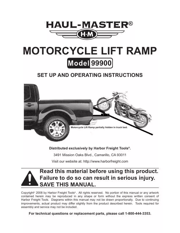
Motorcycle Lift Ramp partially hidden in truck bed.
distributed exclusively by Harbor Freight Tools®. 3491 Mission Oaks Blvd. , Camarillo, CA 93011 Visit our website at: http://www. harborfreight. com
Read this material before using this product. Failure to do so can result in serious injury. SAvE THIS MAnuAL.
Copyright© 2008 by Harbor Freight Tools®. [. . . ] (See Figure E. ) four Hex Sleeves (56), and four Flat Washers (53). IMPORTANT: The Rivet Nuts (57) must be installed directly on the sheet metal truck bed with no plastic or bed FIguRE F liner material between the Nut and BOLT the metal. diagram. ) Route the long wires (26A) from the Winch Solenoid Box (25A) to the truck's battery terminals. Refer to your truck manufacturer's recommendations for routing the Cables. diagram. ) Cut the long wires from the Winch Solenoid Box (26A) to length and atPage 8
guIdE BLOCK (15)
BOLT (16) LOCK nuT (7)
LOng guIdE ROd (20)
19. Remove the Rear Slide Wheels (27) from the Slide Base (21). Slide the Wheel Bracket Assembly (39) into the Slide Base (21) tracks. Re-install the Rear Slide Wheels (27) into the Slide Base (21). Re-install the Winch's Nylon Guide Wheel (9) located on the Front Mounting Channel. Attach the Steel Cable (15A) to the Wheel Bracket Assembly (39) using one Bolt (37), two Large Washers (38), and one Lock Nut (7). Make sure to route the Steel Cable over the Nylon Guide Wheel (9) near the Winch, and under the Slide Wheel SKU 99900
3.
4.
For technical questions, please call 1-800-444-3353.
tach them to the truck's battery terminals, making sure to connect to the correct polarity. (RED wire to Positive +, BLACK wire to Negative --) (See Assy. Insert the Winch Remote Control (27A) into the Connector on the Solenoid Box Assembly (25A). diagram. ) Check to make sure the Winch winds up the Steel Cable (15) when you press the RED Button on the Remote Control (27A). diagram. ) Check to make sure the Winch unwinds the Steel Cable (15A) when you press the BLACK Button on the Remote Control (27A). diagram. )
2.
Check the Winch Remote Control (27A) by briefly pressing the BLACK Button and then the RED Button. The RED Button causes the Winch to reel in. The BLACK Button causes the Winch to reel out. diagram. ) While unreeling the Winch with the BLACK Button, pull the Large Slide Base (21) from the truck bed. The Large Slide Base will hit an internal stop when it is fully extended. diagram. ) Install a Small Lock Pin (51) prior to loading the Slide Base (21). (See Figure I. )
3.
6.
7.
4.
OPERATIng InSTRuCTIOnS
Read the EnTIRE IMPORTAnT SAFETY InFORMATIOn section at the beginning of this manual including all text under subheadings therein before set up or use of this product. [. . . ] Remove any load on Motorcycle Lift before service.
PARTS LIST - WInCH COMPOnEnTS
Part # 1A 2A 3A 4A 5A 6A 7A 8A 9A 10A 11A 12A 13A 14A description Clutch Handle Bolt (M6 x 16) Gear Housing (Clutch Side) Snap Ring Cam Follower Sun Gear (Stage 2) Planet Gear (Stage 3) Nylon Ring Planet Gear (Stage 2) Square Nut Drum Support Drum Bushing Tie Rod Drum Qty. 1 8 1 1 1 1 1 1 1 4 2 2 2 1 Part # 15A 16A 17A 18A 19A 20A 21A 22A 23A 24A 25A 26A 27A description Steel Cable Steel Ball (#6) Drive Shaft Clutch Return Spring Planet Gear (Stage 1) Sun Gear (Stage 1) Gear Housing (Motor Side) Copper Bushing Motor Long Bolt Solenoid Box Assy. 1 1 1 1 1 2 1 1 1 2 1 1 1
SKU 99900
For technical questions, please call 1-800-444-3353
Page 16
ASSEMBLY dIAgRAM - WInCH COMPOnEnTS
15A 16A
8A 5A 6A 7A
9A
11A 10A
13A 12A
14A
24A 23A 22A 2A 21A
4A 2A 1A 3A
20A 12A 10A 18A 17A 11A 19A
25A
27A
26A
SKU 99900
For technical questions, please call 1-800-444-3353
Page 17
PARTS LIST - LIFT RAMP COMPOnEnTS
Part # 1 2 3 4 5 6 7 8 9 10 11 12 13 14 15 16 17 18 19 20 21 22 23 24 25 26 27 28 29 description Base Frame Winch Assy. (2500 Lb. ) Winch Mounting Plate Bolt (M8 x 20) Bolt (M10 x 40) Nut (M10) Lock Nut (M12) Bolt (M12 x 120) Nylon Guide Wheel Bolt (M8 x 25) 12V~ Solenoid Assy. [. . . ]
DISCLAIMER TO DOWNLOAD THE USER GUIDE CHICAGO 99900 Lastmanuals offers a socially driven service of sharing, storing and searching manuals related to use of hardware and software : user guide, owner's manual, quick start guide, technical datasheets...manual CHICAGO 99900


