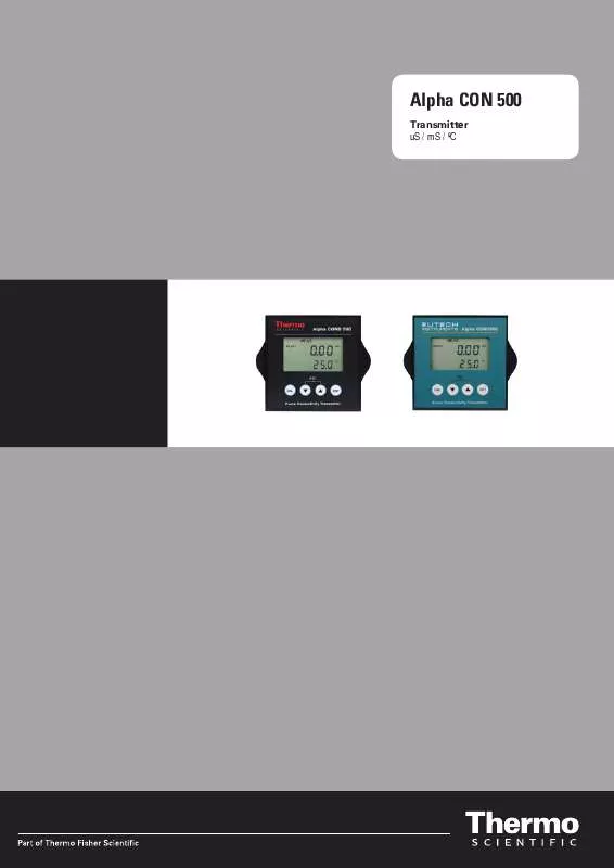
Detailed instructions for use are in the User's Guide.
[. . . ] Alpha CON 500
Transmitter uS / mS / ºC
ROSS and the COIL trade dress are trademarks of Thermo Fisher Scientific Inc. patent 6, 793, 787.
AQUAfast, Cahn, ionplus, KNIpHE, No Cal, ORION, perpHect, PerpHecT, PerpHecTion, pHISA, pHuture, Pure Water, Sage, Sensing the Future, SensorLink, ROSS, ROSS Ultra, Sure-Flow, Titrator PLUS and TURBO2 are registered trademarks of Thermo Fisher.
1-888-pHAX-ION, A+, All in One, Aplus, AQUAsnap, AssuredAccuracy, AUTOBAR, AUTO-CAL, AUTO DISPENSER, Auto-ID, AUTO-LOG, AUTO-READ, AUTOSTIR, Auto-Test, BOD AutoEZ, Cable-Free, CERTI-CAL, CISA, DataCOLLECT, DataPLUS, digital LogR, DirectCal, DuraProbe, Environmental Product Authority, Extra Easy/Extra Value, FAST QC, GAP, GLPcal, GLPcheck, GLPdoc, ISEasy, KAP, LabConnect, LogR, Low Maintenance Triode, Minimum Stir Requirement, MSR, NISS, One-Touch, One-Touch Calibration, One-Touch Measurement, Optimum Results, Orion Star, Pentrode, pHuture MMS, pHuture Pentrode, pHuture Quatrode, pHuture Triode, Quatrode, QuiKcheK, rf link, ROSS Resolution, SAOB, SMART AVERAGING, Smart CheK, SMART STABILITY, Stacked, Star Navigator 21, Stat Face, The Enhanced Lab, ThermaSense, Triode, TRIUMpH, Unbreakable pH, Universal Access are trademarks of Thermo Fisher.
Guaranteed Success and The Technical Edge are service marks of Thermo Fisher.
PerpHecT meters are protected by U. S. PerpHecT ROSS electrodes are protected by U. S. ORION Series A meters and 900A printer are protected by U. S. [. . . ] The minimum allowable calibration point is 10% of the full scale reading of the range selected. 6.
1413
1578
S
Press the ENTER key to confirm the calibration value and to return to the measurement mode.
Note: To exit this program without confirming the calibration, press the and keys together (Escape). Note: When there is a calibration error, the buffer icon and ERR annunciator will appear together with a blinking electrode icon. Press both and keys together TWICE to return to the measurement mode.
6
ADVANCED SETUP FUNCTIONS
The advanced setup mode lets you customize your transmitter's preferences and defaults. This transmitter features different sub groups that organize all setup parameters. The sub-groups are:
6. 1
Range and Zooming Selection Setting
Your COND 500 transmitter provides six selections of conductivity measurement ranges to suit your process application needs. Zooming selection is available where both the 4 mA and 20 mA output current can be assigned to specific conductivity values for a more refined output. Press the ENT key to enter the setup mode. Transmitter displays `SEt rng' indicating the range setup mode. The display will show the last set conductivity measurement range. Use the or keys to scroll through the six ranges and press the ENT key to select your desired range. The transmitter will now switch to the zooming selection and display the low zoom value setup.
SETUP
HOLD
SETUP
HOLD
2. 3.
1. 9 99
1
S
NOTE: Range 6 selection page will only appear in the setup mode when the cell constant is selected as K = 1. 0 or K = 10. Range 1 will only appear when cell constant is selected as K =0. 1 or K =1. 0
Six Range selection
4.
For zooming setting, use the or keys to set the conductivity low zoom value for the 4 mA current and press the ENT key to confirm. The transmitter now displays the high zoom value setup. Use the or keys again to set the conductivity high zoom value for the 20 mA current and press the ENT key to confirm and return to the range setup mode. Press both and keys together to return to the measurement mode.
SETUP
HOLD
0. 00
L
S
5.
SETUP
HOLD
1. 9 99
Hi
S
6.
6. 2
Temperature Compensation Setting
Conductivity readings are affected by temperature. Under varying temperature conditions, use ATC to compensate for the conductivity values. If temperature of sample is constant, and a temperature sensor/probe is not available, Manual Temperature Compensation can be utilized. 6. 2. 1 Automatic Temperature Compensation
For automatic temperature compensation (ATC) selection, connect the ATC sensor to the transmitter, as described in Section 2. 2. 2. Press the ENT key to enter the setup mode. Use the or keys to scroll o through the sub-menus till LCD displays `SEt C'. [. . . ] Re-wire loop cables with correct polarity. Ensure that sample entirely covers the probe sensors. a) Ensure shield wire is properly connected to pin 7 a). a) Ensure temperature sensing cable are making good contact a) Ensure calibration standard solution is not contaminated. [. . . ]


