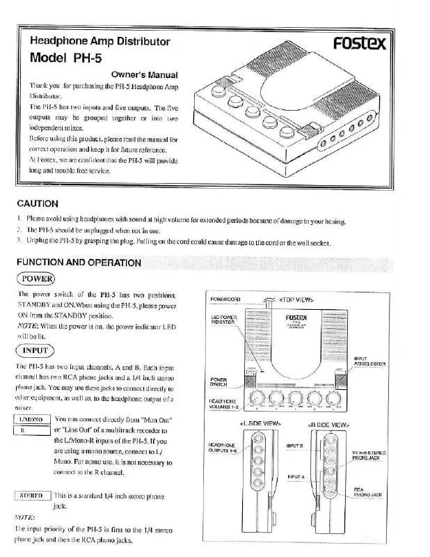
Detailed instructions for use are in the User's Guide.
[. . . ] Water and Moisture - The appliance should not be used near water - for example, near a bathtub, washbowl, kitchen sink, laundry tub, in a wet basement, or near a swimming pool, and the like. Carts and Stands - The appliance should be used only with a cart or stand that is recommended by the manufacturer. Heat - The appliance should be situated away from heat sources such as radiators, heat registers, stoves, or other appliances (including amplifiers) that produce heat. [. . . ] Grounding or Polarization - The precautions that should be taken so that the grounding or polarization means of an appliance is not defeated. Power Cord Protection - Power supply cords should be routed so that they are not likely to be walked on or pinched by items placed upon or against them, paying particular attention to cords at plugs, convenience receptacles, and the point where they exit from the appliance. Cleaning - The appliance should be cleaned only as recommended by the manufacturer. Nonuse Periods - The power cord of the appliance should be unplugged from the outlet when left unused for a long period of time. Object and Liquid Entry - Care should be taken so that objects do not fall and liquids are not spilled into the enclosure through openings. Damage requiring Service - The appliance should be serviced by qualified service personnel when: A. The power supply cord or the plug has been damaged; or B. Objects have fallen, or liquid has been spilled into the appliance; or C. The appliance has been exposed to rain; or D. SPECIFICATIONS
INPUT SECTION
INPUT (Balanced) Connector Input level Impedance INPUT (Unbalanced) Connector Input level Impedance CHANNEL INPUT Connector Input level Impedance AUX INPUT Connector level Impedance XLR ( Hot : Pin 2 ) / Stereo phone ( Hot : tip ) +4dBu / -10dBV(switchable) 10 k or more RCA pin -10dBV 10 k or more RCA pin -10dBV 10 k or more RCA pin -10dBV 10 k or more
OUTPUT SECTION
PHONES 1-5 Connector Max. Output Level Load Impedance Frequency Response S/N Distortion CASCADE OUT Connector Output level Frequency Response S/N Distortion Click Noise (Power on / off) Shock Noise Peak LED Indication Stereo phone 500 mW or more ( 32 load, Distortion 3. 0 % or less ) 8 ~ 32 30 ~ 20 kHz ± 2dB ( 32 load, 1kHz, 200 mW ) -65dBV or less (DIN AUDIO, OUTPUT VR : MIN) -80dBV or less ( IHF-A, OUTPUT VR : MIN) 0. 1 % or less ( 32 load, 1kHz, 200 mW ) RCA pin -10dBV ± 3dB (INPUT VR : CAL ) 30 ~ 20 kHz ± 1dB -85dBV or less (DIN AUDIO, OUTPUT VR : MIN) -90dBV or less ( IHF-A, OUTPUT VR : MIN) 0. 05 % or less ( 1kHz, -10dBV ) -20dBVp-p or less (OUTPUT VR : MIN) -40dBVp-p or less (Measure noise level when one side of appliance is dropped 3 times from 5 cm height. ) +7dBV ± 3dB
GENERAL
Dimensions Weight Power supply JPN USA/CND EUR/UK Power consumption 210 (W) × 200 (D) × 43 (H) mm 1. 9 kg 100 VAC, 50/60 Hz 120 VAC, 60 Hz 230 VAC, 50/60 Hz 8W
* Specifications and appearance are subject to change without notice for product improvement. CONTROLS, INDICATORS & CONNECTORS
< Front Panel >
1
2
3
4
5
5
5
5
5
5
PH-5
HEADPHONE AMP DISTRIBUTOR
0 10 0 10 0 10 0 10 0 10 0 10
PEAK
5 CAL
POWER
1
2
3
4
5
AUX IN
ST MONO PHONES
0
10
INPUT
5
1. Headphone output level control knob [PHONES 1-5] AUX input level control knob [AUX IN] Peak LED [PEAK] Power LED [POWER] 5. 8.
6
7
8
Headphone jacks [PHONES 1-5] Input image position selector switch [ST/MONO] Input master level control knob [INPUT] Power switch [POWER]
< Rear Panel >
9
10
1
2
CHANNEL IN 3
(-10dBV)
INPUT 5 L
(+4dBu/-10dBV)
4
R
XLR PHONE 2 T HOT 3 R COLD 1 S GND
L
R
L (-10dBV) R CASCADE OUT
L
(-10dBV)
R
INPUT
L/MONO AUX IN
R
(-10dBV)
+4dBu
-10dBV
11
9. 12.
12
13
14
15
Channel input jacks [CHANNEL IN 1-5] Balanced input connector (XLR) [INPUT] Cascade output jack [CASCADE OUT] Unbalanced input jack [INPUT]
13. Balanced input level selector switch [-4dBu/-10dBV] 15. Balanced input connector (Stereo phone) [INPUT]
5
PH-5
3. EXPLODED VIEW, PCB ASSEMBLY AND PARTS LIST
PH-5 OVERALL EXPLODED VIEW & PARTS LIST
Ref. [. . . ] Description 8221262000 CASE, COVER, PH-5 8221264000 PANEL, FRONT, PH-5 8274174000 PCB Assy, MAIN, PH-5 8650800000 CORD, AC, USA/CND 8650801000 CORD, AC, EUR 8650802000 CORD, AC, UK 5 6 7 8650803000 CORD, AC, JPN 8207000208 BUSHING, SR-4N-4 8218775001 INSULATION SHEET, PH-5 8228775002 INSULATION SHEET B, PH-5 12 13 14 15 Ref. Description 8274175000 PCB Assy, VR, PH-5 8226198003 ROTARY, KNOB(C), G 8226198001 ROTARY, KNOB(A), R 8242256003 TRANS, POWER, 120V 8242256006 TRANS, POWER, 230V~ 8242256010 TRANS, POWER, 100V 8221263000 CHASSIS, MAIN, PH-5 8253014007 SW, WL, PUSH, POWER, SDDLB-SPST 8207000318 PLASTY-FOOT, 3725 8226228000 BUTTON, PUSH, POWER
BBT 3x6 BZn
BBT 3x6 BZn
BBT 3x6 BZn BBT 3x6 BZn BBT 3x6 BZn
BBT 3x8 BZn
BBT 3x8 BZn
BBT 3x8 BZn
6
B 3x6 CZn
BBT 3x6 BZn
PH-5
PH-5 Parts List
· MAIN/VR PCBs
RESISTORs ICs Ref. Description U101~501 8236035803 IC, µPC4570HA U102~502 8236046000 IC, NJM386BD U152~552 8236046000 IC, NJM386BD U601 U602 U605 U651 U701 U801 U802 8236035803 IC, µPC4570HA 8236035803 IC, µPC4570HA 8236035803 IC, µPC4570HA 8236035803 IC, µPC4570HA 8236035803 IC, µPC4570HA 8236032005 IC, REGULATOR, NJM78M12FA 8236034705 IC, REGULATOR, 79M12FA Ref. [. . . ]


