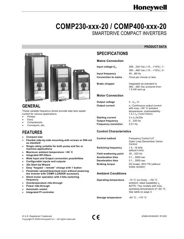
Detailed instructions for use are in the User's Guide.
[. . . ] Registered Trademark Copyright © 2009 Honeywell Inc. · All rights reserved
EN0B-0638GE51 R1009
SmartDrive COMPACT VARIABLE FREQUENCY DRIVES
Air quality Chemical vapors Mechanical particles Altitude
Analog output IEC 721-3-3, unit in operation, class 3C2 IEC 721-3-3, unit in operation, class 3S2 100% load capacity (no derating) up to 1000 m 1% derating for each 100 m above 1000 m; max. 2000 m 0. . . 95% RH, non-condensing, non-corrosive, no dripping water 3. . . 150 Hz Displacement amplitude 1(peak) mm at 3. . . 15. 8 Hz Max acceleration amplitude 1 g at 15. 8. . . 150 Hz UPS Drop Test (for applicable UPS weights) Storage and shipping: max 15 g, 11 ms (in package) IP20 Digital outputs Relays
0(4). . . 20 mA; RL max. [. . . ] The mounting dimensions are also given on the back of the inverter.
Screw mounting Fig. Mounting with screws or DIN-rail
DIN-rail mounting
Mechanical size MI1 MI2 MI3
H1 156. 5 195 262. 5
H2 147 183 252. 3
H3 137. 3 170 241. 3
W1 65. 5 90 100
W2 37. 8 62. 5 75
W3 4. 5 5. 5 5. 5
D1 98. 5 101. 5 108. 5
D2 7 7 7
Fig. Dimensions in millimeters
COOLING
Forced air flow cooling is used in all SmartDrive Compact drives. Enough free space shall be left above and below the inverter to ensure sufficient air circulation and cooling. SmartDrive Compact products can be mounted side by side. You will find the required dimensions for free space and cooling air in the tables below:
Mechanical size MI1 MI2 MI3 Mechanical size MI1 MI2 MI3 Free space above [mm] 100 100 100 Cooling air required [m3/h) 10 10 30 Free space below [mm] 50 50 50
5
EN0B-0638GE51 R1009
SmartDrive COMPACT VARIABLE FREQUENCY DRIVES
CABLING AND FUSES
Use cables with heat resistance of at least +70 °C. The cables and the fuses must be dimensioned according to the following tables. The fuses function also as cable overload protection. These instructions apply only to cases with one motor and one cable connection from the inverter to the motor. In any other case, ask the technical support for more information. Connection Mains cable Motor cable Control cable Cable type Power cable intended for fixed installation and the specific mains voltage. (NKCABLES/MCMK or similar recommended) Power cable equipped with compact low-impedance shield and intended for the specific mains voltage. (NKCABLES /MCCMK, SAB/ÖZCUY-J or similar recommended). 360º grounding of both motor and FC connection required to meet the standards. Screened cable equipped with compact low-impedance shield (NKCABLES /Jamak, SAB/ÖZCuY-O or similar).
Cable and fuse sizes for 208-240 V 1~/3~ inverters (COMP230-. . . )
Size Type (power) IN [A] Fuse [A] Mains cable Cu 2 [mm ] Terminals cable size (min/max) Main terminal 2 [mm ] 1, 5 4 1, 5 4 1, 5 6 Earth terminal 2 [mm ] 1, 5 4 1, 5 4 1, 5 6 Control terminal 2 [mm ] 0, 5 1, 5 0, 5 1, 5 0, 5 1, 5 Relay terminal 2 [mm ] 0, 5 1, 5 0, 5 1, 5 0, 5 1, 5
MI1 MI2 MI3
P37 P75 -1P5 2P2
1, 7 3, 7 4, 8 7, 0 9, 6
10 20 32
2 x 1, 5 + 1, 5 2 x 2, 5 + 2, 5 2x6+6
Cable and fuse sizes for 380-400 V 3~ inverters (COMP400-. . . )
Size Type (power) IN [A] Fuse [A] Mains cable Cu 2 [mm ] Terminals cable size (min/max) Main terminal 2 [mm ] 1, 5 4 1, 5 4 1, 5 6 Earth terminal 2 [mm ] 1, 5 4 1, 5 4 1, 5 6 Control terminal 2 [mm ] 0, 5 1, 5 0, 5 1, 5 0, 5 1, 5 Relay terminal 2 [mm ] 0, 5 1, 5 0, 5 1, 5 0, 5 1, 5
MI1 MI2 MI3
P55 - P75 1P1 - 2P2 3P0 - 5P5
1, 9 3, 3 4, 3 5, 6 7, 6 - 12
6 10 20
3 x 1, 5 + 1, 5 3 x 1, 5 + 1, 5 3 x 2, 5 + 2, 5
MAINS MAINS MOTOR
MOTOR
Mechanical size MI1
Fig. SmartDrive Compact power connections
Mechanical size MI2-3
EN0B-0638GE51 R1009
6
SmartDrive COMPACT VARIABLE FREQUENCY DRIVES
Control cable tightening torque: 0. 4 Nm Strip the plastic cable coating for 360° grounding
Fig. SmartDrive Compact control connections wiring
Fig. SmartDrive Compact control connection terminals The table below shows the SmartDrive Compact control connections with the terminal numbers.
Terminal +10Vre AI1 GND 24Vout GND DI1 DI2 DI3 A B AI2 GND GND DI4 DI5 DI6 AO DO RO11 RO12 RO21
RO22 RO23
1 2 3 6 7 8 9 10 A B 4 5 13 14 15 16 18 20 22 23 24 25 26
Signal Ref. [. . . ] Useful function when commissioning and testing applications
30 s Start-up wizard
"Keypad Remote" Operation
Quick Setup Menu
Parameter upload/download with COMP-LOADER
Only the most commonly used parameters visible in basic view to Easy navigation through the provide easier navigation. The full view can be seen after P13. 1 most common parameters Parameter conceal is deactivated by changing the value to 0. Parameter copying easily from 1 inverter to another Parameter sets can be uploaded and downloaded with this tool. [. . . ]


