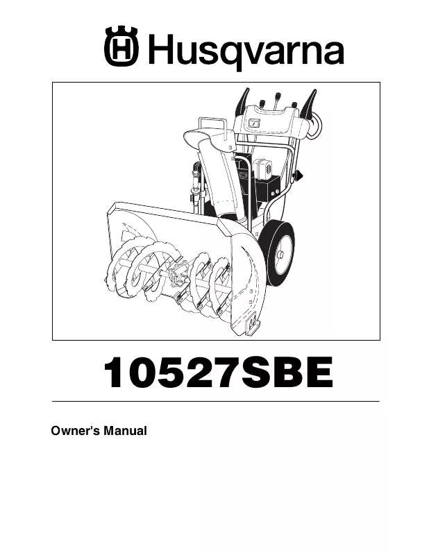
Detailed instructions for use are in the User's Guide.
[. . . ] 10527SBE
Owner's Manual
IMPORTANT
Safe Operation Practices for Walk-Behind Snow Throwers
This snow thrower is capable of amputating hands and feet and throwing objects. Failure to observe the following safety instructions could result in serious injury. Look for this symbol to point out important safety precautions. WARNING: Always disconnect spark plug wire and place it where it cannot contact plug in order to prevent accidental starting when setting up, transporting, adjusting or making repairs. [. . . ] Disconnect the power cord from the receptacle first, then from the engine. Allow the engine to warm up for a few minutes. Engine will not develop full power until it has reached normal operating temperature. WARM START - ELECTRIC STARTER Follow the steps above, keeping the choke control in the OFF position. Insert safety ignition key (packed separately in parts bag) into ignition slot until it clicks. Keep the extra safety ignition key in a safe place. Place throttle control in FAST position. Push the primer four (4) times if the temperature is below 15°F, or two (2) times if temperature is between 15° and 50°F. If temperature is above 50°F, priming is not necessary. NOTE: Over priming may cause flooding, preventing the engine from starting. If you do flood the engine, wait a few minutes before attempting to start and DO NOT push the primer. When the engine starts, release the recoil starter handle and slowly move the choke control to the OFF position. Allow the engine to warm up for a few minutes. Engine will not develop full power until it has reached normal operating temperature. WARM START - RECOIL STARTER Follow the steps above, keeping the choke in the OFF position. BEFORE STOPPING Run the engine for a few minutes to help dry off any moisture on the engine. To avoid possible freeze-up of the starter, proceed as follows: 13 ELECTRIC STARTER 1. Plug the other end of the power cord into a three-hole grounded 120 Volt A. C. While the engine is running, push starter button and spin the starter for several seconds. NOTE: The unusual sound made while starter is spinning will not harm the engine or starter. Disconnect the power cord from the receptacle first, then from the engine. While the engine is running, pull the recoil starter handle with rapid, full arm strokes three or four times. [. . . ] NO.
WHEELS / DECALS
SNOW THROWER - MODEL NO. 961 93 00-09
DESCRIPTION
1 2 3 4 7 8 9 10 11 12 13 14 15 16 17 18 19 20 21 22 23 24 25 26 27 28 29 30 31 32 33 34
532 19 95-01 532 15 54-43 532 19 21-09 532 18 44-71 871 21 06-16 532 18 78-59 532 18 78-58 817 60 04-06 817 49 05-08 532 19 57-49 532 19 95-19 532 18 20-15 532 19 95-18 532 19 95-12 532 19 95-11 532 18 18-47 532 08 51-79 532 18 41-97 532 19 21-26 532 18 24-66 532 18 76-22 532 19 49-41 532 17 91-39 532 19 49-40 532 18 92-82 532 17 46-97 532 17 98-30 532 19 38-85 532 19 95-02 532 70 02-79 812 00 00-45 532 14 63-15
Wheel Assembly, 12", Power Steering, LH Pin, Klik 1/4 Cover, Power Steering Bolt, Shoulder #10-24 x 5/8 Capscrew, Hex Head, Flanged 3/8-16 x 1 Bracket, Steering Cable, RH Bracket, Steering Cable, LH Screw, Hex Head 1/4-20 x 3/8 Screw, Hex Head 5/16-18 x 1/2 Link, Steering Lever Yoke, Steering Pin, Steering Lever Bellcrank Bracket Assembly, LH Steering Bracket Assembly, RH Steering Pin, Steering Bellcrank Retainer, Hairpin Bracket, Steering Driver, Wheel Ring, Wire Retainer Lobe, Wheel Slide, Clutch Spring, Clutch Slide Lobe, Axle Key, Square Washer, Thrust (1") Bearing, Axle Spring, Return Wheel Assembly, 12", Power Steering, RH Clip, Retainer Ring, Retaining Screw, Hex Head 5/16-18 x 5/8
KEY PART NO. NO.
DESCRIPTION
1 2 3 4 5 6 7 8 9 10 11 12 13 --
532 18 10-38 532 19 13-78 532 18 10-34 532 18 10-41 532 19 87-45 532 18 10-32 532 15 57-98 532 15 58-00 532 18 10-36 532 18 37-29 532 18 39-07 532 18 39-05 532 15 57-94 532 19 93-96
Decal, Danger Decal, Husqvarna Decal, Danger, Deflector Decal, Danger Decal, Husqvarna, 10527SBE Decal, Instruction Decal, Traction Lever Decal, Auger Lever Decal, Speed Control Decal, Remote Deflector Decal, LH Trigger Decal, RH Trigger Decal, Husqvarna, Crown Owner’s Manual
NOTE: All component dimensions given in U. S. 1 inch = 25. 4 mm IMPORTANT: Use only Original Equipment Manufacturer (O. E. M. ) replacement parts. [. . . ]


