User manual HUSQVARNA DUMP FROM SEAT
Lastmanuals offers a socially driven service of sharing, storing and searching manuals related to use of hardware and software : user guide, owner's manual, quick start guide, technical datasheets... DON'T FORGET : ALWAYS READ THE USER GUIDE BEFORE BUYING !!!
If this document matches the user guide, instructions manual or user manual, feature sets, schematics you are looking for, download it now. Lastmanuals provides you a fast and easy access to the user manual HUSQVARNA DUMP FROM SEAT. We hope that this HUSQVARNA DUMP FROM SEAT user guide will be useful to you.
Lastmanuals help download the user guide HUSQVARNA DUMP FROM SEAT.
Manual abstract: user guide HUSQVARNA DUMP FROM SEAT
Detailed instructions for use are in the User's Guide.
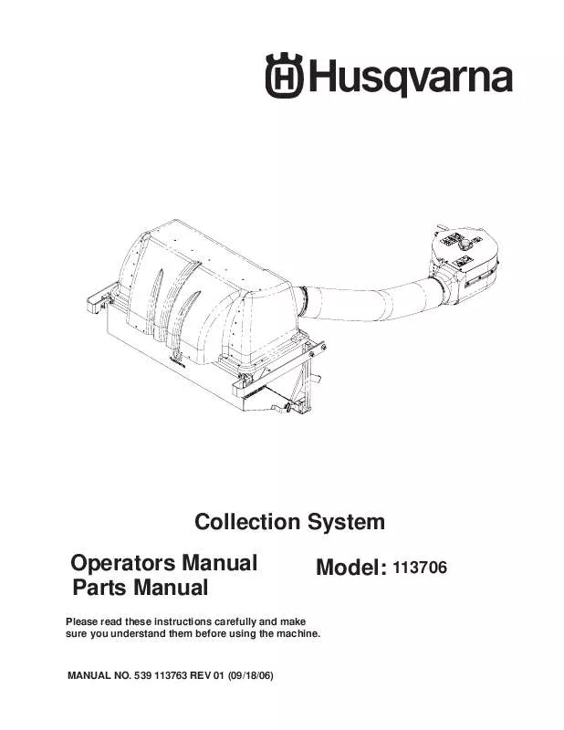
[. . . ] Collection System Operators Manual Parts Manual Model: 113706
Please read these instructions carefully and make sure you understand them before using the machine.
MANUAL NO. 539 113763 REV 01 (09/18/06)
©2006 Husqvarna. Printed in U. S. A.
2
INDEX
Operators Guide Features and Controls . . . . . . . . . . . . . . . . . . . . . . . . . . . . . . . . . . . . . . . . . . . . . . . . . . . . . . . . . . . . . . 4 General Information . . . . . . . . . . . . . . . . . . . . . . . . . . . . . . . . . . . . . . . . . . . . . . . . . . . . . . . . . . . . . . . . . [. . . ] • Keep all parts in good working condition and all hardware tightened. Replace all worn or damaged decals.
6
ASSEMBLY Assembly Instructions
For iZ Models with a Kawasaki engine and vertical muffer only.
You must obtain a muffler kit Part No. 539 113780, from your dealer prior to installing the collection system. Slide right guard to second set of holes gine exhaust flange of any residual gasattach with original hardware. Remove hardware on upper right guard the spacers on the inside of the frame, on the engine shield and retain. Remove hardware from the upper right See illustration. Install new muffler with new gaskets provided.
ENGINE SHIELD
REPLACE SPACER TO INSIDE
REMOVE HARDWARE
UPPER RIGHT GUARD
REMOVE HARDWARE
7
ASSEMBLY Assembly Instructions
Front Weight Bar For iZ Models
Tools Required: Ratchet with 5/16” Socket 5/16” Wrench Mounting Instructions • Remove mower foot plate and floor pan. • Align weight bar to the front of the frame. • Secure weight bar to mower frame with four 5/16-18 x 1 1/4” hex bolts from kit, reuse the four 5-16” washers and four 5/16” nyloc nuts that were removed from the foot plate. • Place all front weights on front weight bar. • Place holddown bar over front weights and secure to front weight bar using two 3/8” x 1” clevis pins and two hair pins. • Reinstall floor pan.
WEIGHT BAR HOLD DOWN
FRONT WEIGHT BAR
CAST COUNTERWEIGHT
8
ASSEMBLY Assembly Instructions
Front Weight Bar For LZ Models
Tools Required: Ratchet with 3/8” Socket 3/8” Wrench Mounting Instructions • Using the weight keepers, attach front weight bar to mower at the front caster arms. • Secure front weight bar to mower frame with four 3/8” x 1 1/4” hex bolts, four 3/8” flat washers, and four 3/8” nyloc nuts. • Place all front weights on front weight bar. • Place holddown bar over front weights and secure to front weight bar using two 3/8” x 1” clevis pins and two hair pins.
WEIGHT BAR HOLD DOWN
CAST COUNTERWEIGHT
FRONT WEIGHT BAR
9
ASSEMBLY Assembly Instructions
Collection System
Tools Required: Ratchet Torque Wrench 1/2" Wrench 1/2" Socket 9/16" Wrench 9/16" Socket 5/8" Socket (2) 3/4" Wrench 3/4" Socket Flat Screw Driver 5/32" Allen Wrench Hacksaw 11/32" Drill Bit Drill
HITCH BRACKET SUPPORT BRACKET
LZ MODLES
1. Open the mounting kit box and remove all of the components. Place the support bracket on the frame and secure with (2) 990563, 3/8 x 1 bolts and (2) 976979, 3/8 nyloc nuts. Place the hitch brackets on the frame and secure with (3) 990622, 1/2 x 1 1/4 bolts and (3) 101331, 1/2 nyloc nuts. Figure 1.
3.
SUPPORT BRACKET
HITCH BRACKET
iZ MODLES
FIGURE 1
4.
Place the hitch assembly on the ground behind the mower. Place the (2) hitch pins thru the hitch and the hitch brackets. Secure the hitch pins with the (2) hairpins that are secured with the (2) lanyards. Figure 2.
LANYARD
HITCH ASSEMBLY
HITCH PIN
FIGURE 2 10
ASSEMBLY
5. [. . . ] Turn engine off and remove the spark plug wire.
PROBLEM
POSSIBLE CAUSE
CORRECTION
Loss of Vacuum.
1. Loosen bolts.
Unusual vibration or noise.
Unit difficult to close.
1. Obstructions keeping door from completely closing. Hood hinge bolts too tight.
20
SPINDLE DRIVE ASSEMBLY
NOTE: Your Front Weight Bar may look different from those shown in this diagram.
21
HOPPER ASSEMBLY
39 37 36 38
43
16 9 30 23 4 5 16 42 10 17 2 3 20 44 46 20 44 14
26 17 12 35 33 22 1 33 2 41 2 41 25 29 14 47 2 6 24 20 7 44 2 27 19 13 25
REF.
45
40 25 34
15
31
24
21 25 34 11 32 23
29 18
17 2 16 28 20
8
44
22
HOPPER ASSEMBLY
ITEM PART NO. [. . . ]
DISCLAIMER TO DOWNLOAD THE USER GUIDE HUSQVARNA DUMP FROM SEAT Lastmanuals offers a socially driven service of sharing, storing and searching manuals related to use of hardware and software : user guide, owner's manual, quick start guide, technical datasheets...manual HUSQVARNA DUMP FROM SEAT


