User manual LIFT-MASTER 535-315LM
Lastmanuals offers a socially driven service of sharing, storing and searching manuals related to use of hardware and software : user guide, owner's manual, quick start guide, technical datasheets... DON'T FORGET : ALWAYS READ THE USER GUIDE BEFORE BUYING !!!
If this document matches the user guide, instructions manual or user manual, feature sets, schematics you are looking for, download it now. Lastmanuals provides you a fast and easy access to the user manual LIFT-MASTER 535-315LM. We hope that this LIFT-MASTER 535-315LM user guide will be useful to you.
Lastmanuals help download the user guide LIFT-MASTER 535-315LM.
Manual abstract: user guide LIFT-MASTER 535-315LM
Detailed instructions for use are in the User's Guide.
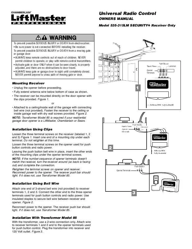
[. . . ] NOTE: Transformer Model 85 is required if your residential garage door opener is a LiftMaster, Chamberlain or Sears.
®
1
Antenna Wire Fully Extended
Installation Using Clips
Loosen the three terminal screws on the receiver (labeled 1, 2 and 3) Figure 1. Insert one end of a mounting clip under each terminal. Loosen the three terminal screws on the opener used for push button controls and radio power. Leaving the push button bell wire in place, insert the other ends of the mounting clips under the opener terminal screws. [. . . ] SPECIFICATIONS Output Rating. . . . . . . . . . . . . . . . . . . . . . . . . . . . . . . . . . . . . . 5 Amps 28VAC or DC Max. Power . . . . . . . . . . . . . . . . . . . . . . . . . . . . . . . . . . . . . . . . . . . . . . . . . . . . 18V - 30V ~, 30mA, 60Hz 18 - 30V , 30mA RF Frequency. . . . . . . . . . . . . . . . . . . . . . . . . . . . . . . . . . . . . . . . . . . . . . . . . . . . . . . . . . . . . . . . . . . . 315MHz If the power is other than shown in specifications, Accessory Transformer Model 85 or 95 is required. Accessory Transmitters -- Series 50, 60, 70, 80 and 900.
NOTICE: To comply with FCC and or Industry Canada (IC) rules, adjustment or modifications of this receiver and/or transmitter are prohibited, except for changing the code setting or replacing the battery. THERE ARE NO OTHER USER SERVICEABLE PARTS. Tested to Comply with FCC Standards FOR HOME OR OFFICE USE. Operation is subject to the following two conditions: (1) this device may not cause harmful interference, and (2) this device must accept any interference received, including interference that may cause undesired operation.
114A2578D
© 2006 The Chamberlain Group, Inc. All Rights Reserved
M
Universal Radio Control
MANUAL DEL PROPIETARIO
IA
ADVERTENCIA ADVERTENCIA
Para prevenir LESIONES GRAVES o MUERTE posible por electrocución: · Asegurase que la electricidad no está conectasa ANTES de instalar el receptor. Para evitar posibles LESIONES GRAVES o incluso la MUERTE con el movimiento del portón o la puerta de cochera. · Mantener SIEMPRE los controles remotos fuera del alcance de los niños. No permitir NUNCA que los niños operen, o jueguen con transmisores de control remoto. · Activar la entrada o puerta SÓLO cuando pueda verse claramente, esté bien ajustada, y no haya obstrucciones al recorrido de la puerta. · Mantener SIEMPRE la entrada o puerta del garaje a la vista hasta que esté completamente cerrada. NUNCA permitir que alguien cruce la trayectoria de una entrada o puerta móvil.
Modelo 535-315LM SECURITY Receptor Solamente
PRECAUCIÓN
Electricidad Botón de radio Terminales del Abridor
Común
®
1
Montaje del Receptor
· Desenchufar el abridor antes de proceder. · Extender completamente el cable de la antena por debajo de la casa según ilustrado. · El receptor puede montarse directamente en el abridor de la puerta con los broches provistos. O · Fijo a un cielorasoi/pared interior del garaje con cable de timbre conectado (no provisto). Fijar el receptor al cieloraso o pared interior del garaje con los tornillos para tabiques de yeso y catón provistos. NOTA: Se Requiere el Transformador Modelo 85 si el Abridor de Garaje Residencial es LiftMaster, Chamberlain o Sears.
Cable de Antena Completamente Extendida
Electricidad de radio Terminales del Abridor
Botón
Común
3 21
®
Instalacion Usando Broches
Aflojar los tres tornillos terminales en el receptor (rotulados 1, 2 y 3) Figura 1. Insertar un extremo de un broche de montaje debajo de cada terminal. Aflojar los tres tornillos terminales en el abridor usado para los controles de botones y electricidad para el radio. Dejando el cable de timbre a botón en su lugar, insertar los otros extremos en los broches de montaje bajo los tornillos terminales del abridor. NOTA: Si la secuencia numérica de los terminales del abridor no corresponde con el receptor, girar el receptor (de manera que la parte postterior mire hacia afuera) y completar la conexión. [. . . ] Con el puente en la posición "M" (Momentánea), los contactos se cierran por 1/4 de segundo sin importar la duración de la transmisión radial. Con el puente en la posición "C" (Constante), los contactos permanecen cerrados mientras la radio continúa transmitiendo. El receptor está graduado de fábrica a M.
ESPECIFICACIONES Clasificación nominal de salida . 18V a 30V ~, 30mA, 60Hz , 30mA 18V a 30V Frecuencia . [. . . ]
DISCLAIMER TO DOWNLOAD THE USER GUIDE LIFT-MASTER 535-315LM Lastmanuals offers a socially driven service of sharing, storing and searching manuals related to use of hardware and software : user guide, owner's manual, quick start guide, technical datasheets...manual LIFT-MASTER 535-315LM


