User manual LIFT-MASTER SL500
Lastmanuals offers a socially driven service of sharing, storing and searching manuals related to use of hardware and software : user guide, owner's manual, quick start guide, technical datasheets... DON'T FORGET : ALWAYS READ THE USER GUIDE BEFORE BUYING !!!
If this document matches the user guide, instructions manual or user manual, feature sets, schematics you are looking for, download it now. Lastmanuals provides you a fast and easy access to the user manual LIFT-MASTER SL500. We hope that this LIFT-MASTER SL500 user guide will be useful to you.
Lastmanuals help download the user guide LIFT-MASTER SL500.
Manual abstract: user guide LIFT-MASTER SL500
Detailed instructions for use are in the User's Guide.
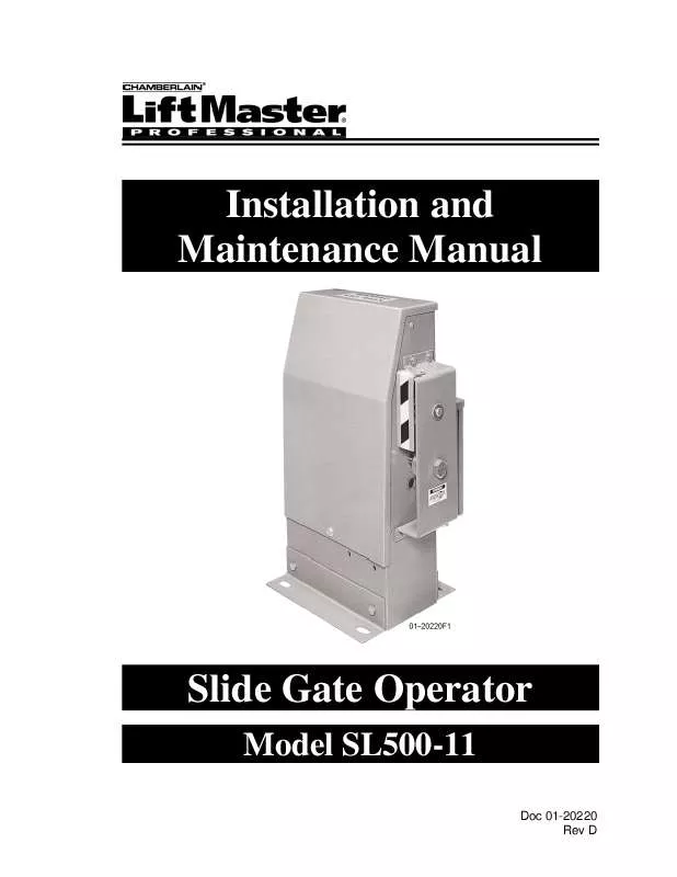
[. . . ] Installation and Maintenance Manual
Slide Gate Operator
Model SL500-11
Doc 01-20220 Rev D
2
Contents
Contents
General Information ____________________________________________ 4
Supplied Parts ___________________________________________________________ 4 Cycle Rate ______________________________________________________________ 4 Specifications ___________________________________________________________ 5 Dimensional Outline ______________________________________________________ 5
Safety Information ______________________________________________ 6
Safety Instructions________________________________________________________ 6 Safety Precautions for Open-Roller Gates and Ornamental "Grill Type" Gates ________ 8
Preparing the Installation _______________________________________ 10
Pre-installation Check List ________________________________________________ 10 Wiring Specifications ____________________________________________________ 10 Operator Features _______________________________________________________ 11 Programmable Features___________________________________________________ 14 Led Descriptions ________________________________________________________ 15
Installation ___________________________________________________ 16
Step 1: Step 2: Step 3: Step 4: Step 5: Step 6: Step 7: Step 8: Step 9:
Mounting Legs __________________________________________________ 16 Pedestal Post (Optional) ___________________________________________ 17 Mounting ______________________________________________________ 18 Gate Brackets ___________________________________________________ 18 Drive Chain_____________________________________________________ 19 Chain Guards ___________________________________________________ 19 Battery Install ___________________________________________________ 20 Electrical Power Connections_______________________________________ 21 Programming ___________________________________________________ 22
Step 10: Limit Switch Adjustments _________________________________________ 27 Step 11: Preliminary System Check-Out _____________________________________ 28 Step 12: Accessory Installation_____________________________________________ 28
Required Maintenance__________________________________________ 30
Doc 01-20220 Rev D
Contents
3
Troubleshooting _______________________________________________ 31
1. Power ______________________________________________________________ 31 2. Accessories__________________________________________________________ 32 3. Programs/Features ____________________________________________________ 32 4. [. . . ] The program LED will turn off, indicating that you a re out of the program mode. The board will reset as if first powered on.
ADJUSTMENT FOR AUDIBLE WARNING SOUND LEVEL AUDIBLE WARNING SOUNDER
PROGRAM EXT. RUN OBSTRUCTION
RIGHT HAND
INDICATOR L. E. D. s (Light Emitting Diode)
CLOSING
OPENING
POWER
FUNCTION & OPTION DISPLAY PANELS
01-20220f17
FUNCTION & OPTION PROGRAMMING BUTTONS
Figure 15
Doc 01-20220 Rev D
Installation
23
PROGRAM 1 RIGHT HAND/LEFT HAND OPERATION
Program 1 determines whether the operator is "right handed" or "left handed". To determine which type your gate controller needs to be set to, observe the installation from the operator side of the gate. 0 = NOT SELECTED OPERATOR WILL NOT FUNCTION IN THIS MODE 1 = RIGHT HANDED OPERATOR WILL MOVE GATE FROM LEFT TO RIGHT TO OPEN 2 = LEFT HANDED OPERATOR WILL MOVE GATE FROM RIGHT TO LEFT TO OPEN If the operator is on the right side of the opening, the operator is "right handed". If the operator is on the left side of the opening, it is "left handed". 1 Press the FUNCTION select button to set the function to "1". Option "0" is the factory setting and does not allow gate movement. 2 Pressing the "OPTION" button will change the option between "1" and "2". When the correct option for your application is indicated, press the "FUNCTION" select button to save this selected option and to step to the next program. The option display will show a "0", "1" or "2". This option must be changed to either a "1" for right hand or "2" for left hand.
PROGRAM 2 MASTER/SLAVE OPERATION
Program 2 selects whether the installation is a single operator or dual operators with common controls. 0 = SINGLE GATE OPERATOR INSTALLATION 1 = MASTER GATE OPERATOR 2 = SLAVE GATE OPERATOR 1 If the "FUNCTION" display shows "2", proceed on as follows. The "OPTION" display will indicate a "0", "1" or "2". The "0" option is the factory setting and is for single operator gates. Press the "OPTION" select button to change the option between "0", "1" or "2", where option "1" is for master operation. If it does not show "2" then press the "FUNCTION" select button to set the display to "2". The "0" option can be changed to "1" or "2" for dual gate operators.
2
3
Doc 01-20220 Rev D
24
Installation IMPORTANT: Once all programming is completed for the master operator, you must then program all features for the slave operator. All nine (9) programs should be the same except for Program 1 (R. H. /L. H. ). In most cases one unit will be right handed and the other will be left hand. Program 3 (Gate obstruction sensitivity). In some cases the two gates will require different settings. [. . . ] LIMIT SWITCH - Single pole double throw (S. RD. T. ), 15 amp. to 12 v. d. c. , reverse voltage = 50 volt. hour = 6. 5, maximum charging volts = 13. 7, battery storage info = 6 months c~ 68 degrees F = 80% voltage, 12 months © 68 c~rees F = 63% voltage. Amp hours = Battery will supply 1 amp, for 6 1/2 hours, or 1/2 amp. [. . . ]
DISCLAIMER TO DOWNLOAD THE USER GUIDE LIFT-MASTER SL500 Lastmanuals offers a socially driven service of sharing, storing and searching manuals related to use of hardware and software : user guide, owner's manual, quick start guide, technical datasheets...manual LIFT-MASTER SL500


