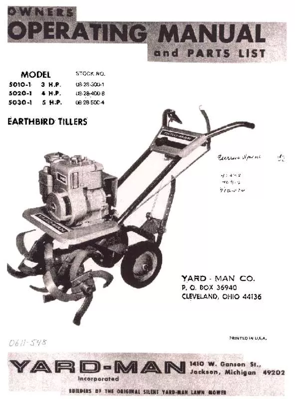
Detailed instructions for use are in the User's Guide.
[. . . ] ' ' sparki:l"u9 wire be'r~re atte~Ptil:l9 ', ' "
ALWAYS STOP ENGINE any repairs or adjustMents.
~f1d discorynect
DIS~NGAGE ALL CLvtCHES:an~ shift ;n~o neutral bef91'6' ~tarting'. m'otQr. Keep hands, feet and cjt)tl'\iri9aw~y from power cjrlVt:nparts, ';, ' ", , ' ST ART THE ENGINE tAREF~t:LV A!W8Y:S s~and at side of maCl:1lne: Do not operate engine indoor$witlio~~pioper ve~. t:ila~i~n:, -, , : " :, DISENGAGE POWER AND SrOPMOTO(:t'before re:m~v, inQ'Qbstatles. -Qr when leaving oPfJrQting Position. ' , ', -' " . ' :, DO NOT ALLOW MINO~S toopera:t~ , m:achirie urile:5$~tiorou9hJV iostructed and properly supeNised, ": c,
, " , " " , " , '
9. iO.
KEEP CHILDREN NEveA
AND PETS ~W~Y, f~m~Qtati~i3
f, ft'tes. [. . . ] Placeth. ~ h~dl~ grips ov~r:th~ end~ o(the hand)e tubes. 4, Place;one , end af ~e IT)ast~rclutch . rod tt)roughtt:ie, hol~ at the bo~tom of the master clutch con1:roland the other end thr9ugb the hole in '!he tlipper heat the end of the left handlE!tube and $ecur¥. 5, The tilling width is, ass~mbl~d fot 22" as, shippeq. For 11" tilling width r&move hair-pin and clevis pin arid piJll Qutsrd~:Spool AS$smt;Jlies fr:6m stiaft;Replace clevis pina!'ld hair-pin thru in5id~ Spool Assemblies and Shaft, 6. Attath the depth bat releas~handle to tbehandJei near the right handle grip with 8' slC)tte~ headscr~w ~rid nut. Attach the upper dep'thbeT' relebse rod to the handle by hooking the loop~ end th~Qughthe ~at on the handle from the outside, Attach the opposite end down through the round h?le In t~e depth bar pivot plate, SecL)re witt1 i cotter pJn. Atta<J!:1 the double bend enQ of ". the lower trip rod down through the slotted hole in the p. ivot plate: S~cure ~)th ~ wa~her andc9tter pin. . Adjust; ment Link on t:he opposite end and ad;ustto align With hole in . Oepth Bar La~ch. Che9K operat\on of Oep'th Bi)t ReleaseHandl& aft~r:attaching rods, With Depth ~at Release Hanc!le @!ithe wuy uP. Attach the depth ~r Into the bracket at the rear of the tiller frame using the short clevis p\n through one of the holes m the 'bar, s~cur'ingloVith the hair pin cotter. Use the pointed end of the d~Pth bar in the ground except when ~h~IoIse 1he furrow plow IS ~esired, of
Adju$1ment ~jnk,
BlfGR:£stARTlHG £"61"1.
1. Fill the fuel tank With ~ good , grade of regular 9a. sollne. Plac~ m~chine on 9 level surface, Remove oil filler cap and fill cr~n~~s!'J'. . ""ith909(;j quality geterger'lt. . oit. Above 32~F use :SAE . ~O~;, ~el~w 32°;:yse SAE l()W. Fill t6 over: f. ll::i~i!iga:~d r~p. lace~ap; : " 3.
be ch~ck~9
p~riO'q, ;W, e off lel/el should -': "~4. Che£1<. Oil 'I$y:&1evef:Y five {5Y, op~rat!n~ 'hours 9r eachtime, I'rI&(i"'jn~
oftery. ~ ;
b~rir:, g
Irijti~(:iBr:eak. in. ', ':
i$ usl:id.
,
"NtINE
Shift the master, clut~h, C4h:t;rol to , th'e neutral position. Move the speed c::ontrQIl~ve1'to 'fUI'1chok~ posi'tiQr1\Start
the engine by -pJllih9 tapidly 91'1~h~, r~cpil;starter rciee- A$
the engine ~t~rt~ ~1id' begins towariri up gradually teturn the c:ontroi lev, rt<i1hede;sir~~ tp~~~;po~ition, If the engin~ shouJd-fa:il ~o ~t_~;:rff:er to your :engine
Instruct{()" Manual; . .
5TOP";'-6 E"GJN'f
S~()P: the'~~Sin:e m~\ie the:spee~ cpntrC1t Jever t(> thestOI?
po~i~ion:. 'YhQ sparkplug wir~ mii~ also be rerno, vE!d to
prevent accid~ntal s:rarting while llnattended.
OF CONTROLS
MASTII CLUT(M (0"TI01
maSter clutch control is'\oc~red '-on the handle panel assembly a~d is used to engage , th~: f~rward and reverse belt idlers. Move , t~e clutch :con~r9Ifu~ward tP engagetheforward , belt Idle/'" Pul1the"clutch~cir'ltr~1 'h:ick to thecel:'ter position: for neutral. Pull the c(uttthcontroj back and:hold , for reverse. Operat~ t!ie 'ciutcti , ~ol1trQI several times'until the neutral poslt!on' cal'j be :~asjlydetermined for the cOf)~rol '" should always be in this ;Pos1tion befo~estartil:'lg ~, rygine.
DEPTH 8AR
Before tilling lock depth bar in vertical position, al, ds~$ke imosoil. Adjust bar depth'to suit soil col:lditions, and depth of tilling. [. . . ] >I 1-1/8 Pulley, Idler w/H. . . b Washer, Idler Pullev Bracket, 6elt Restrictor $crQw, Set. 1\ 1. 1/2 L8elt, 4t. -4001Spec;ial)
"V" Pulley
QTV.
1
,
4 1
1 , 1 1 1
10
1 1
4
4
2
, ~
1
3
1
2
6
, 2
1
2
f 1
68
~9
90 91
92
2153:'
40201
40032
'509, 31
22568 60319
93
94 95
S'84tJ
96 97
98 99
60199
1529':39
15Q9~112 20100 42238
100 101 102
103 104 105
42239 22520
16$3~15
1625-27
1539. 24
4()148
1Q6 107 108 109
110
603:02
2251'8 40225
60n,
42210
40211
111 112 113
114
400e;5 422Q1
422)1
"5 116
117 118 119
120
6115~
40286 4Q. 120
42332-
61822
42330
Bracket, Belt Restrictor (Reyerse) Belt, 4L. 450 (SPecial~ Pullev, Flat 6olt, ~e~ He~. 5/16-18 x 5/8 ~racket, Belt Guide Auy. , Clutch lOCk, Out AS$y" Reyef5e Arm Bolt, Carri~ (Sh. Sq, Nacl<l 5/16 x 2" AsSV. , ldlerPutley (Flatl BOlt, Hel< H~eQ (Grade 5) 5/16. 18 )( 2" Cap, Handle Socket H'Indie (RH. I Handle (L. . H. I ROd, Clutch ROd, Lower TriP Link, Rod AdJu$tment, 6/16. 18 T Pu~h Nut. [. . . ]


