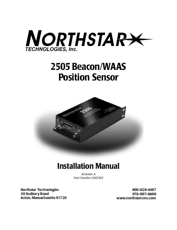
Detailed instructions for use are in the User's Guide.
[. . . ] 2505 Beacon/WAAS Position Sensor
Installation Manual
Revision A Part Number GM2505
Northstar Technologies 30 Sudbury Road Acton, Massachusetts 01720
800/628-4487 978/897-6600 www. northstarcmc. com
Limited warranty policy
Northstar Technologies, Inc. warrants the Northstar 2505 to be free from defects in materials and workmanship for a period of two (2) years. This warranty applies to the original purchaser and to any subsequent owner during the warranty period, which begins on the date of shipment of the unit, F. O. B. Acton, Massachusetts, to an authorized Northstar dealer. [. . . ] Unauthorized tampering will automatically void the warranty.
Choosing the 2505's mounting location
The 2505 is housed in a rugged aluminum enclosure with a mounting flange, gaskets, and watertight connectors. The 2505 itself is water-resistant, but not waterproof, so mount it where water won't contact it directly or enter it by following power or antenna cables. Tie-wrap all cables to keep them secure, and if cables are shortened, lengthened, or re-terminated, seal all wiring splices.
Mounting the 2505
You can mount the 2505 horizontally or vertically, using the appropriate mounting holes; see Figure 1 on page 14. Keyhole slots at the rear will help if you're installing the 2505 where access is limited and it may be difficult to start the mounting screws at the obstructed end. Securely tighten all mounting screws to avoid vibration-related problems.
2505 INSTALLATION MANUAL, Revision A
Page 13
SECTION TWO Installing and interfacing the 2505
Figure 1: 2505 case and mounting dimensions
Connecting the 2505 to power
WARNING!
Be sure to ground the equipment to prevent electrical shock and mutual interference. Be sure that the power supply's voltage is compatible with the 2505's voltage rating (10 to 40 volts DC). Connecting to the wrong power supply can result in fire or damage to equipment.
CAUTION!
Before applying power to the 2505, double-check all the wiring. A small, but significant number of units sustain damage due to incorrectly wired connections. Such damage is not covered under warranty. Be sure you don't apply primary voltage directly to any of the 2505's signal input/output wires as this may vaporize circuit board conductors in the 2505.
Page 14
2505 INSTALLATION MANUAL, Revision A
SECTION TWO Installing and interfacing the 2505
The 2505 requires 10 to 40 volts DC at approximately 10 watts. The power supply is protected against reverse-polarity power inputs. The 2505 has an internal ½-amp fuse. If you connect pin 12 to a switched source of +5 to +40 volts DC, the 2505 will turn on whenever that voltage source is applied. Power to the 2505 can be wired in either of two ways:
·
For permanent power-on in which there's no remote-on output available from the host device, connect pin 12 to pin 25. As long as power is connected to pin 25, the 2505 will remain on. For remote turn-on by the host device, connect pin 12 to any host-switched +5V to +40 volts DC output of the GPS host. In this configuration, the 2505 will turn on or off whenever the host device is turned on or off.
·
Installing the AN205-P antenna
The 2505 operates exclusively with Northstar's AN205-P combination GPS/DGPS antenna. This "combo" antenna provides an easier and more attractive installation than those that use separate GPS and DGPS antennas. In many cases, the loop antenna design also improves noise rejection of beacon signals and provides better performance. For quick and easy connection, the 2505 uses an internal antenna splitter to separate the signal path of the one coaxial cable coming from the AN205-P antenna.
2505 INSTALLATION MANUAL, Revision A
Page 15
SECTION TWO Installing and interfacing the 2505
7. 00
2. 5
Use the locking nut shown to prevent rotation of the antenna or bottoming of the mounting stanchion into the threaded mount portion of the antenna. If done with enough force, either of these may break the antenna.
TNC
3. 5
Figure 2: Northstar AN205-P antenna dimensions
Choosing the antenna's mounting location
Mount the antenna near the top of the vehicle, where an unobstructed view of the horizon is available in all directions, but mount it lower than any high-power transmitting antennas, such as radar or satcom. Keep the antenna at least six feet away from objects that can "shade" GPS or differential signals. [. . . ] PRN numbers of satellites used in solution (null for unused fields). Mode: 1 = fix not available 2 = 2-D 3 = 3-D Mode: M = manual, forced to operate in 2-D or 3-D mode A = automatic, allowed to automatically switch 2-D/3-D
3.
Example: $GPGSA, A, 3, 14, 22, 03, 09, 08, 29, 17, , , , , , 2. 7, 2. 2, 1. 6*3A<CR><LF> Mode: SVs Used: PDOP: HDOP: VDOP: automatic/3-D PRNs 14, 22, 03, 09, 08, 29, 17 2. 7 2. 2 1. 6
2505 INSTALLATION MANUAL, Revision A
Page 41
Appendix C NMEA output protocol
GPS satellites in view
Number of SVs in view, PRN numbers, elevation, azimuth and SNR values. Four satellites maximum per transmission, additional satellite data sent in second or third sentence.
HEADER
CONTENTS OF DATA FIELDS
$GPGSV, x, x, xx, xx, xx, xxx, xx. x. . . . . . . . . . . , xx, xx, xxx, xx. x*hh<CR><LF>
4th SV 2nd to 3rd SV SNR1 azimuth, degrees2 elevation, degrees3 satellite PRN number total number of satellites in view message number, 1 to 3 total number of messages, 1 to 3 1. SNR (C/No) 00. 0-99. 9 dB, null when not tracking Azimuth, range 000 to 359 degrees Elevation, range 00 to 90 degrees
Examples:
$GPGSV, 2, 1, 06, 03, 12, 238, 06. 0, 07, 82, 008, 15. 5, 11, 04, 053, , 27 , 43, 178, 12. 3*67<CR><LF>
Messages Msg. [. . . ]


