Detailed instructions for use are in the User's Guide.
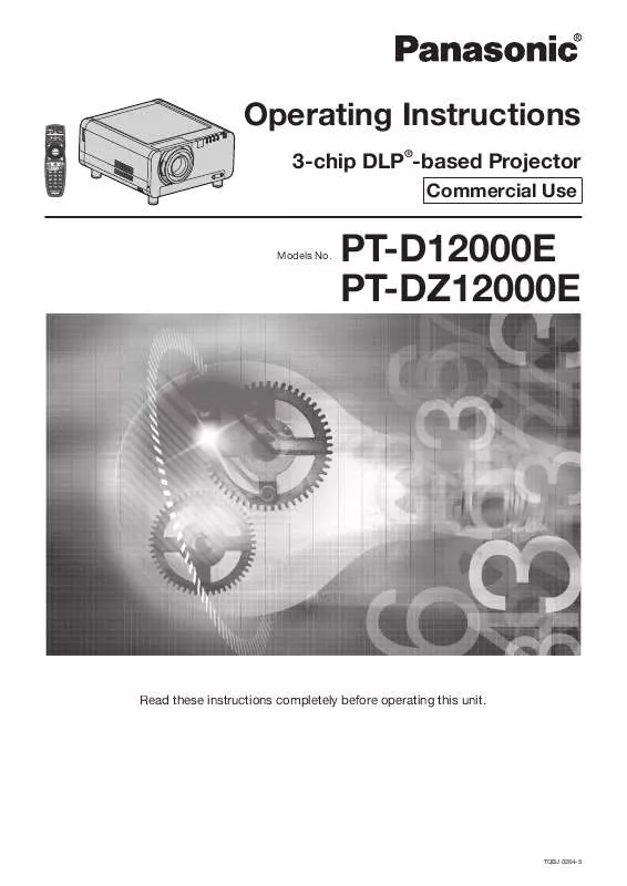
[. . . ] Operating Instructions
3-chip DLP®-based Projector
Commercial Use
Models No.
PT-D12000E PT-DZ12000E
Read these instructions completely before operating this unit.
TQBJ 0264-5
Dear Panasonic Customer:
This instruction booklet provides all the necessary operating information that you might require. We hope it will help you to get the most performance out of your new product, and that you will be pleased with your Panasonic ® DLP based projector. The serial number of your product may be found on its back. You should note it in the space provided below and retain this booklet in case service is required. [. . . ] · ON: When the tilting inside the unit is to be used for the tilting of the edge blending area. · USER: When a specific tilting is to be used for the tilting of the edge blending area. (Separate software is required to establish these settings. Consult your dealer. )
Green line Red line
9. Press to select "BRIGHT ADJUST".
RIGHT MARKER BRIGHT ADJUST OFF OFF
3. Press ENTER.
· The "EDGE BLENDING" screen will be displayed.
EDGE BLENDING UPPER START ON 0
66 ENGLISH
10. Press ENTER.
· The "BRIGHT ADJUST" screen will be displayed.
BRIGHT ADJUST BRIGHT INSIDE BRIGHT OUTSIDE
18. Press to select an item, and press to adjust the setting.
Projection Edge blending width (right) range BRIGHT adjustment (right)
11. Press to select "BRIGHT INSIDE". Press ENTER.
· The "BRIGHT INSIDE" adjustment screen will be displayed.
BRIGHT INSIDE INTERLOCKED WHITE RED GREEN BLUE ON
Marker
· When "INTERLOCKED" is set to "OFF", individual adjustment of "RED", "GREEN" and "BLUE" will be possible.
Note
· The BRIGHT adjustment is a function for making the brightening of the BRIGHT level in those areas where the pictures overlap less conspicuous when multi-screens have been configured using edge blending. The optimal point is where, after the BRIGHT INSIDE has been adjusted, the compensation amount is the same for the BRIGHT levels in the areas where the pictures overlap and where the pictures do not overlap. If, after the BRIGHT INSIDE adjustment, only the vicinity of the borders of the areas where the pictures overlap and where the pictures do not overlap becomes bright, proceed to adjust the top, bottom, left and right widths. Alternatively, if only the vicinity of the borders has darkened as a result of the width adjustments, proceed with the BRIGHT OUTSIDE adjustment. · When a rear screen or screen with a high gain is used, the joints may appear to be discontinuous depending on the viewing position.
13. Press to select an item, and press to adjust the setting.
· Once adjustment is complete, press MENU to return to "BRIGHT ADJUST".
14. Press to select the part of "UPPER", "LOWER", "RIGHT", "LEFT". Use to adjust the width for correcting the "BRIGHT INSIDE" setting (0 to 255). Press to select "BRIGHT OUTSIDE".
BRIGHT INSIDE BRIGHT OUTSIDE OUTSIDE AREA
Frame delay
When 1 080/60i, 1 080/50i and 1 080/24sF signals are being input, this simplifies image processing so that the frame delay for pictures can be shortened.
17. Press ENTER.
· The "BRIGHT OUTSIDE" adjustment screen will be displayed.
BRIGHT OUTSIDE INTERLOCKED WHITE RED GREEN BLUE ON 0 0 0 0
1. Press to select "FRAME DELAY".
EDGE BLENDING FRAME DELAY RASTER POSITION OFF DEFAULT
· When "INTERLOCKED" is set to "OFF", individual adjustment of "RED", "GREEN" and "BLUE" will be possible.
ENGLISH 67
Basic Operation
0 0 0 0
BRIGHT OUTSIDE BRIGHT INSIDE
How to use ADVANCED MENU (continued) 2. Press to switch "FRAME DELAY".
· The setting will change as follows each time is pressed.
DEFAULT SHORT
When 16:9 pictures are displayed (when HDTV or 480p pictures are input or 16:9 is selected in the SIZE mode)
Pressing button will move the image upward.
· DEFAULT: This is the standard setting. · SHORT: This causes the pictures to be delayed after the audio.
Pressing button will move the image downward.
Note
· When "FRAME DELAY" is set to "SHORT", deterioration in the picture quality will occur. [. . . ] · Character "i" that follows the number of displayed dots stands for interlace signal. · Flicker (line flicker) will be caused in images if interlace signals are connected.
ENGLISH 123
Information
Appendix (continued)
List of P IN P
Subwindow
RGB input RGB1 YPbPr input RGB input RGB2 YPbPr input VIDEO input S-VIDEO input DVI Moving image system*3 RGB system*4 AUX ET-MD77DV ETET-MD77SD3/ MD77SD1 ET-MD100SD4*1 Moving image *2 system RGB system*4
Main window
RGB input RGB1 YPbPr input RGB input RGB2 YPbPr input VIDEO input S-VIDEO input Moving image system*3 DVI RGB system*4 ET-MD77SD1 ET-MD77SD3/ ET-MD100SD4*1 AUX ETMD77DV Moving image system*2 RGB system*4
× × × ×
× × × × × × × × × ×
× × × ×
× × × × × × × × × ×
× × × × × × × ×
× × × × × × × ×
× × × × × × × × ×
× ×
× × × × × × × × ×
× × × × × × × × ×
× × × × × × × × ×
× × × ×
: P IN P (Picture in Picture) combinations are enabled ×: P IN P (Picture in Picture) combinations are disabled *1 Only 480i, 576i, 720/60p, 720/50p, 1 035/60i, 1 080/60i, 1 080/50i, 1 080/24sF, 1 080/30p, 1 080/25p, and 1 080/24p are supported. *2 Only 480p, 576p, 720/60p, 720/50p, 1 080/60i, 1 080/50i, 1 080/24sF, 1 080/30p, 1 080/25p, 1 080/24p, 1 080/60p, and 1 080/50p are supported. *3 Only 480p, 576p, 720/60p, 720/50p, 1 080/60i, 1 080/50i, 1 080/24sF, 1 080/24p, 1 080/25p, 1 080/30p, 1 080/50p, and 1 080/60p are supported. [. . . ]


