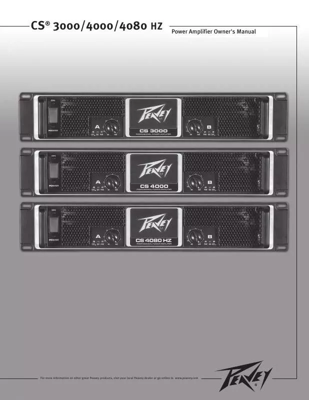
Detailed instructions for use are in the User's Guide.
[. . . ] For more information on other great Peavey products, visit your local Peavey dealer or go online to www. Intended to alert the user to the presence of uninsulated "dangerous voltage" within the product's enclosure that may be of sufficient magnitude to constitute a risk of electric shock to persons. CAUTION: To reduce the risk of electric shock, do not remove cover. WARNING: To prevent electrical shock or fire hazard, this apparatus should not be exposed to rain or moisture, and objects filled with liquids, such as vases, should not be placed on this apparatus. [. . . ] In this mode, both channels operate independently of each other, with their input attenuators controlling their respective levels. Both input connectors are then strapped together and drive both channels with the same input signal. Because both connectors are strapped together, either connector can be used with a patch cable to drive the input of another amplifier. output connections are the same as in Stereo mode. Both input attenuators remain active when in Parallel mode, allowing you to set different levels for each channel. Power and other general performance specifications are the same as in Stereo mode. Bridged Mono Operation Both amplifier channels can be bridged together to make a very powerful single-channel monaural amplifier. Use extreme caution when operating in the bridged mode; potentially lethal voltage may be present at the output terminals. Only channel A's input attenuator is active while in Bridge Mono mode. Both connectors are strapped together, so either connector can be used with a patch cable to drive the input of another amplifier. Unlike the stereo mode, in which one side of each output is at ground, both sides are hot in bridged mode. Channel A's side is the same polarity as its input with the minimum nominal load impedance being 4 ohms (equivalent to driving both channels at 2 ohms) in bridged mode. Driving bridged loads of less than 4 ohms will activate the DDTTM circuitry (see Indicators section), resulting in a loss of power, and may also cause a thermal (overheating) overload. If the switch shuts off during normal use, push it back to the ON position once. If the switch will not stay in the ON position, the amplifier needs servicing. input Attenuators (2) Whenever possible , set the attenuators fully clockwise to maintain optimum system headroom. The input attenuator controls (one for channel A, one for channel B) located on the front panel attenuate signal level (decrease gain) for the respective amplifier channels in all modes. MODE select switch connects both input connectors together in parallel. This directs the same input signal to both channels and allows one connector to be used with a patch cable to drive another amplifier. When in the out position, both input connectors operate independently. Do not operate the AMP MODE select switch with the amplifier powered on. These LED indicators inform the user of each channel's operating status and warn of possible abnormal conditions. [. . . ] 1% @ 950 watts per channel from 20 Hz to 20 kHz > - 75 dB @ 1 kHz x 40 (32 dB) > -70 dB @ 1 kHz at rated power @ 8 ohms > -108 dB, "A" weighted referenced to rated power @ 8 ohms 2 ohms rated power 15 k ohms, balanced 1, 540 watts @ 2 ohms, 1, 000 watts @ 4 ohms, 610 watts @ 8 ohms 3, 650 watts @ 2 ohms, 2, 510 watts @ 4 ohms, 1, 535 watts @ 8 ohms Two back panel temperature dependant variable speed 80 mm DC fans 2 front panel attenuators, rear panel Mode switches 2 DDTTM (clip limiting), 2 Signal presence, 2 Active status Thermal, DC, turn-on bursts, subsonic, incorrect loads Combi XLR & 6. 3 mm phone input , Speakon® and Binding Post speaker output , 15 amp IEC mains connector 16 ga. Steel with cast front panel and cast handles 88. 2 ohms rated power 15 k ohms, balanced 1, 825 watts @ 2 ohms, 1, 185 watts @ 4 ohms, 720 watts @ 8 ohms 4, 535 watts @ 2 ohms, 2, 975 watts @ 4 ohms, 1, 835 watts @ 8 ohms Two back panel temperature dependant variable speed 80 mm DC fans 2 front panel attenuators, rear panel Mode switches 2 DDTTM (clip limiting), 2 Signal presence, 2 Active status Thermal, DC, turn-on bursts, subsonic, incorrect loads Combi XLR & 6. [. . . ]


