Detailed instructions for use are in the User's Guide.
[. . . ] IMPORTANT MANUAL
Do Not Throw Away
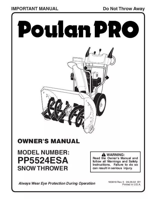
OWNER'S MANUAL MODEL NUMBER:
WARNING:
Read the Owner's Manual and follow all Warnings and Safety Instructions. Failure to do so can result in serious injury.
PP5524ESA
SNOW THROWER
Always Wear Eye Protection During Operation
183618 Rev. 5 09. 26. 02 BY Printed in U. S. A.
SAFETY RULES
Safe Operation Practices for Snow Throwers
IMPORTANT: This machine is capable of amputating hands and feet and throwing objects. Failure to observe the following safety instructions could result in serious injury or death. [. . . ] Wait 5 to 10 seconds between each attempt. When the engine starts, release the starter button and slowly move the choke control to the OFF position. Disconnect the power cord from the receptacle first, then from the engine. Allow the engine to warm up for a few minutes. Engine will not develop full power until it has reached normal operating temperature. WARM START - ELECTRIC STARTER Follow the steps above, keeping the choke control in the OFF position. Insert safety ignition key into the ignition slot until it clicks. Keep the extra safety ignition key in a safe place. Place throttle control in FAST position. Push the primer four (4) times if the temperature is below 15°F, or two (2) times if temperature is between 15° and 50°F. If temperature is above 50°F, priming is not necessary. NOTE: Over priming may cause flooding, preventing the engine from starting. If you do flood the engine, wait a few minutes before attempting to start and DO NOT push the primer. When the engine starts, release the recoil starter handle and slowly move the choke control to the OFF position. Allow the engine to warm up for a few minutes. Engine will not develop full power until it has reached normal operating temperature. WARM START - RECOIL STARTER Follow the steps above, keeping the choke in the OFF position. BEFORE STOPPING Run the engine for a few minutes to help dry off any moisture on the engine. To avoid possible freeze-up of the starter, proceed as follows: 13 ELECTRIC STARTER 1. Plug the other end of the power cord into a three-hole grounded 120 Volt A. C. While the engine is running, push starter button and spin the starter for several seconds. NOTE: The unusual sound made while starter is spinning will not harm the engine or starter. [. . . ] DESCRIPTION
1 2 3 4 6 7 8 9 10 11 12 13 14 15 16 17 18 19 20 21 22 23 24 25 26 27 28 29 30 31 32 33 34 35 36 37 38 39 40 41 42 43 44 46 47 48 49 50 51 52 53 54 55
181044 180522 --74780520 59289 73930500 175330 179092 10040500 150078 184789 85179 178828 183533 150406 179354X008 74780524 175331 180523 74610516 179371 180478 179157 62735 10040600 851084 155452 180465 178830 17490408 179256 179250 180401 179240 73800500 178833X479 179251 179064 178890 76020208 179065 179063X479 74780624 178624X479 71020512 181156 183852X428 178693X428 179068X008 57079 179062 12000010 700279
Spring, Traction Idler Pulley, Idler (2-1/4) Engine, Tecumseh, Model Number OHSK55 (Order parts from Engine manufacturer) Screw, Hex Head 5/16-18 x 1-1/4 Washer, Flat Nut, Jam, Lock 5/16-18 Pin, Idler Pivot V-Belt, Traction Drive Washer, Lock 5/16 Screw, Hex Head 5/16-18 x 3/4 Impeller Idler Arm & Bracket Assembly (Includes Key numbers 8 and 13) Retainer, Hairpin Spring, Brake V-Belt, Impeller Drive Screw, Hex Head 3/8-16 x 1-1/4 Arm, Idler Screw, Hex Head 5/16-18 x 1-1/2 Bushing, Idler Pivot Pulley, Idler (2-3/4) Screw, Hex Head 5/16-18 x 1 Spacer, Engine Pulley Pulley, Engine, Traction Drive Pulley, Engine, Impeller Drive Washer, Flat 3/8 Washer, Lock 3/8 Screw, Hex Head 3/8-24 x 1-3/8 Guide, Belt Cover, Belt Cover, Toolbox Screw, Hex Head 1/4-20 x 1/2 Bolt, Shoulder 5/16-18 Bellcrank Shifter Screw, Hex Head 1/4-28 x 3/4 Arm, Auger Control Nut, Lock 5/16-18 Bellcrank Assembly Link, Speed Control Trunnion, Pivot Bracket Nut, Cage 3/8-16 Pin, Cotter 1/16 x 1/2 Pin, Pivot Bracket Bracket, Bellcrank Screw, Hex Head 3/8-16 x 1-1/2 Pan, Frame Bottom Screw, Hex Head 5/16-18 x 3/4 Nut, Speed 5/16-18 Frame Assembly Plate, Frame End Shaft, Auger Control Washer, Hardened Roller Ring, Retaining Clip, Retainer
NOTE: All component dimensions given in U. S. 1 inch = 25. 4 mm 29
REPAIR PARTS WHEELS / DECALS
SNOW THROWER - MODEL NUMBER PP5524ESA
2
1
4 5
6
4
1 3
2 5
3
1
2 4 9 8
6
5 1 3
30
10
7
REPAIR PARTS WHEELS / DECALS
SNOW THROWER - MODEL NUMBER PP5524ESA
KEY PART NO. NO.
DESCRIPTION
1 2 3 4 5 6
179264 155443 150078 17490508 179830 174697
Wheel Assembly (13") Pin, Klik 1/4 Screw, Hex Head 5/16-18 x 3/4 Screw, Hex Head 5/16-18 x 1/2 Bearing, Axle Washer, Thrust (1")
NOTE: All component dimensions given in U. S. NO.
DESCRIPTION
1 2 3 4 5 6 7 8 9 ---
181037 183884 181035 181042 183883 181033 155798 155800 181039 183618 184741
Decal, Danger Decal, Poulan Pro, 5. 5HP/24" Decal, Danger, Deflector Decal, Danger Decal, Poulan Pro Decal, Instruction Decal, Traction Lever Decal, Auger Lever Decal, Speed Control Owner's Manual, English Owner's Manual, French
NOTE: All component dimensions given in U. S. [. . . ]


