Detailed instructions for use are in the User's Guide.
[. . . ] TM
GX POWER AMPLIFIER SERIES
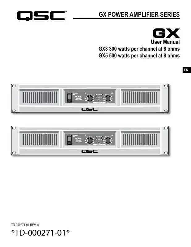
GX3 300 watts per channel at 8 ohms GX5 500 watts per channel at 8 ohms
User Manual
EN
TD-000271-01 REV. A
*TD-000271-01*
IMPORTANT SAFETY PRECAUTIONS AND EXPLANATION OF SYMBOLS
EN
1- Read these instructions. 5- WARNING: To prevent fire or electric shock, do not expose this equipment to rain or moisture. 7- Do not block any ventilation openings. [. . . ] See Troubleshooting if the red LED remains on continuously.
GREEN SIGNAL LEDS
The green LED starts flashing on soft signals (-35 dB), and changes to steady green as the signal level increases.
BLUE POWER LED
The blue PWR (POWER) LED indicates that the AC switch is on, and the amp is receiving power. Within two seconds, it is ready to use.
ALTERNATE GAIN MARKING
When the CROSSOVER switch is active (see rear panel), LF (CH 1) controls low frequencies (subwoofer), HF (CH 2) controls the high frequencies (mid-high box).
REAR PANEL FEATURES
CROSSOVER SWITCH CROSSOVER POSITION
Splits a full-range signal to drive a subwoofer and top box. CH 1 receives the lows, from 20-100Hz, for the subwoofer. CH 2 receives 100Hz to 20kHz, to power a full range speaker. When using CROSSOVER mode, connect signal to CH 1 only. Use the two Gain controls to balance the LF and HF signals (see Front Panel).
6
EXHAUST VENT
Keep vent clear. Install in open-back rack.
EN
FULL RANGE POSITION
For normal, 2-channel use with all inputs active. The crossover is bypassed.
REAR EAR MOUNTING
Rear ears designed for protecting the rear connector wire dressing and supporting the amplifier in a rack. A rear rack support mounting kit (model FG000031-00 pack of two) is available from QSC Technical Services Group.
INPUT CONNECTIONS
BALANCED XLR INPUTS Pin 2 Positive, Pin 3 Negative, Pin 1 Shield (Ground). Recommended for long or short runs, either fixed or frequently changed. Each channel's XLR and TRS jacks are connected internally, and provide feed thru to the other connector. BALANCED 1/4-INCH TRS INPUTS Tip positive, Ring Negative, Sleeve Shield (Ground). Recommended for long or short runs that are frequently changed. UNBALANCED 1/4-INCH TS INPUTS Accepts unbalanced 1/4-inch plugs for short runs. Tip positive, Sleeve Shield (Ground).
UNBALANCED PHONO INPUTS Tip Positive, Barrel Shield (Ground). Recommended for semi-permanent connections to nearby sources, within the same rack. NOTE: when using these inputs, the TRS or XLR inputs should not be used.
7
AC BREAKER RESET
If the amplifier shuts off after a long burst of power, turn off the AC switch and check the circuit breaker. The button can be pressed back in after a 30 second cool-down period. If the breaker trips repeatedly, the amplifier may need servicing.
SERIAL NUMBER AND RATINGS
The rated AC voltage and output power is shown on the serial number plate. Record the serial number in a safe place.
EN
AC INLET SPEAKER CONNECTIONS
BINDING POSTS Accepts banana plugs (not permitted in CE regions). Bare wires or terminals may be inserted into the side holes. 1/4-INCH CONNECTORS Insert plug into the center of the Speakon-Combo jack. [. . . ] If this does not reduce hum, it is coming from the source.
AMPLIFIER NEEDS SERVICING
The following conditions indicate possible unsafe conditions that require service before using. If observed, unplug the AC cord from the wall and when safe, remove the amp for servicing. · If the amplifier emits smoke or burning smells · If the case is severely dented or deformed · If the amplifier is soaked with any fluid · If internal parts sound loose · If the AC breaker trips when power is applied · If the amplifier is dropped, carefully inspect for damage or loose parts before attempting to use.
SPECIFICATIONS
SPECIFICATION SUBJECT TO CHANGE WITHOUT NOTICE.
11
GX3
300 W 350 W 425 W 500 W 200 W 100 dB 1. 2 Vrms 32. 2 dB Class B 6. 3 A 8, less than 0. 05% 4, less than 0. 1% 20 20kHz, +0, -1dB 2dB 100
GX5
500 W 600 W 700 W 850 W 350 W
OUTPUT POWER, 1 kHz, 0. 1 % clipping 8, both channels driven 8, single channel driven 4, both channels driven 4, single channel driven 2, both channels driven, 1% clipping SIGNAL TO NOISE (20 Hz 20 kHz) INPUT SENSITIVITy VOLTAGE GAIN AT 8 OUTPUT CIRCUITRy
EN
34. 4 dB 2-tier Class H 6A
POWER REQUIREMENTS (1/8 power, pink noise at 4 120 V AC) DISTORTION (1 dB below rated power, 20 20 kHz) FREQUENCy RESPONSE DyNAMIC HEADROOM, 4 DAMPING FACTOR INPUT IMPEDANCE MAXIMUM INPUT LEVEL INPUT CONNECTORS, each channel OUTPUT CONNECTORS, each channel AMPLIFIER AND LOAD PROTECTION CONTROLS AND INDICATORS, FRONT PANEL
Greater than 20K ohms (balanced or unbalanced) +24 dB (16 Vrms) 3-pin XLR and 1/4" TRS, balanced, parallel Phono, unbalanced Speakon®, 1/4", Binding Posts Short circuit, open circuit, thermal, RF protection Load protected against DC faults Gain controls, 21 detents Red Clip LEDs, proportional, 0. 1% THD threshold. Green Signal LEDs, threshold -35 dB Blue Power LED, AC-on. [. . . ]


 QSC AUDIO GX5 REV D (10553 ko)
 QSC AUDIO GX5 DATASHEET (381 ko)
 QSC AUDIO GX5 SPECIFICATION SHEET (387 ko)
