User manual SANYO HIT DOUBLE 200 INSTALLATION
Lastmanuals offers a socially driven service of sharing, storing and searching manuals related to use of hardware and software : user guide, owner's manual, quick start guide, technical datasheets... DON'T FORGET : ALWAYS READ THE USER GUIDE BEFORE BUYING !!!
If this document matches the user guide, instructions manual or user manual, feature sets, schematics you are looking for, download it now. Lastmanuals provides you a fast and easy access to the user manual SANYO HIT DOUBLE 200. We hope that this SANYO HIT DOUBLE 200 user guide will be useful to you.
Lastmanuals help download the user guide SANYO HIT DOUBLE 200.
Manual abstract: user guide SANYO HIT DOUBLE 200INSTALLATION
Detailed instructions for use are in the User's Guide.
[. . . ] General Installation Manual
© 2009 January, Sanyo Electric Co. , Ltd. All Rights Reserved 1/1/09
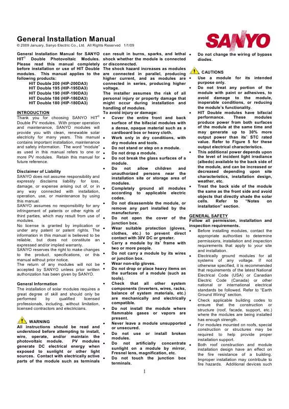
General Installation Manual for SANYO © HIT Double Photovoltaic Modules. Please read this manual completely before installation or use of HIT Double modules. This manual applies to the following products: HIT Double 200 (HIP-200DA3) HIT Double 195 (HIP-195DA3) HIT Double 190 (HIP-190DA3) HIT Double 186 (HIP-186DA3) HIT Double 180 (HIP-180DA3) INTRODUCTION © Thank you for choosing SANYO HIT Double PV modules. [. . . ] Do not use modules of different specifications in parallel. Check and follow all safety precautions of other system components used.
UL Listing Information To satisfy UL standard 1703 requirements, when installing modules, be sure to: · Use only stranded or solid copper singleconductor type UF cable or USE cable, rated sunlight resistant, for modules and interconnect wiring that is exposed to weather. · Observe the requirements described in sections labeled INSTALLTION and SPECIFICATIONS. INSTALLATION General Please read this guide completely before installation or use of the modules. This section contains electrical and mechanical specifications needed before using your SANYO PV modules. · Modules should be firmly fixed in place in a manner suitable to withstand all expected loads, including wind and snow loads. · Metals used in locations that are exposed to moisture shall not be employed alone or in combinations that could result in deterioration. · Install modules where they are not shaded by obstacles like buildings and trees. Especially pay attention to avoid partially shading modules by objects during the daytime. · Modules are water resistant, but not waterproof. Moisture may leak through where the frame and glass connect. · Please contact your SANYO Authorized Representative with questions regarding mounting profiles for modules if needed. Notes on Installation · Clearance between the roof surface and module frame is required to allow cooling air to circulate under the back side of the module. This also allows any condensation or moisture to dissipate. Install modules so that air can circulate between the roof and the module as freely as possible. · Leave 4 inches of clearance between the roof and the module frame. · SANYO recommends (but does not require) the installation method and mounting profile shown in Figure 1.
albedo of surrounding surfaces. A module should be attached on a mount or support structure rail by metal · Please see Figure 5 for the effect of fittings (Size: 27x27x14mm, Material; angles of installation on output power. The metal · The height of a module above a fitting must meet the following surface affects the power potential of specifications. Size: not less than 1. 06'' the module's back face. (27mm) width · When possible, maximize the height of Thickness: not less than 0. 12'' (3 mm) modules above surfaces in order to Material: Stainless steel maximize ambient light beneath the · Bolting torque must be more than 8N. m. · Always position support structures and The following information is provided to rails along the edges of a module, or help customers obtain good performance between modules, and do not allow without exceeding a module's operating rails to shade a module's back surface. [. . . ] · The grounding lead size must be 2 greater than 6mm (No. 10 AWG), and its type shall be sunlight-resistant UF cable or USE-2 cable. · Maximum torque value for the connection must be 2. 7 N. m (24 in-lb).
·
Verify that all fittings are properly installed to protect wires against damage and prevent moisture intrusion.
Bypass Diodes · When modules in series strings are partially shaded, it may cause reverse For further information, please visit voltage across the cells or modules, www. sanyo. com/solar or contact your because the current from other cells in SANYO Authorized Representative. the same series is forced to flow through the shaded area. This may cause undesirable heating to occur. [. . . ]
DISCLAIMER TO DOWNLOAD THE USER GUIDE SANYO HIT DOUBLE 200 Lastmanuals offers a socially driven service of sharing, storing and searching manuals related to use of hardware and software : user guide, owner's manual, quick start guide, technical datasheets...manual SANYO HIT DOUBLE 200


