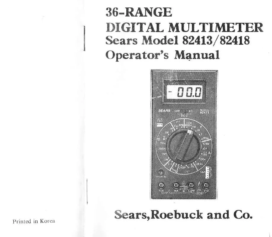
Detailed instructions for use are in the User's Guide.
[. . . ] Do not exceed the limits of tllc tcstcr,
Distribution Circuits Pack a Punch In high energy circuits such as distribution
and bus bars, dangerous arcs
transform. ers
Safety Check
Double check the switch setting, and lcad connections before making measutements. Are you following all of the
instruc tions?
of explosive nature can occur if the circuit is shorted. If the tester is connected across a high energy circuit when set to a 1ow resistance range, a
is
current _range, or any other low impedance range, the circuit
virtually shorted.
Disconnect the tester or turn
off
the
power before
changing switch positions.
Do not connect to circuits with voltage present when switclr is in any ohms or current position. Whcn rcplacing fuses use only specificd type fuses and inscrt in correct fuse notd"j. , , _
is available. [. . . ] PNP)
3.
Set RA, NGE switch to desired , , V', position.
position).
-7-
untill satisfactory reading is obtained.
-""r. r1"rn"rr, factor is not known, set switch to highest "ru range and reduce
of Value not only for this functioniut
If
magnitude
4. Connect test leads
5.
to device or circuit bcing measured.
Turn on power to device or circuit bcing measured. Voltage value wili appear on Digital Display aiong with
the voltage polarity.
DC Current Measurement 1. . Red lead to "mA" jack for measurcrncr)ts rrp to Black lead to "COM" jack.
For measuremenb between 2 Amps and red lead to "l0A" jack.
the resistance being measured. is connected to a circuit, discharge all capacitors before applying test prods, 4. Connect test leads to circuit being measured. q Read resisrance value on Digital Display.
3.
If
turn off power and
2 Amps,
Diode Tests
L. Red lead to , , V. f, )', , Black iead to , , COM". POWER/FUNCTION switch to , . DC 0, ', , and 3, Ifthe
l0
Amps, connect
)
J.
POWER/FUNCTION switch to "I)C ()", rnd RANGE switch to desired "A'' position. Open the circuit to be measured, and conncct test leads IN SERIES with the ioad in which currcnt is to be
measured.
, 4. 5.
is displayed.
RANGE switch to the 2K, e ( +<- ) position. semiconductorjunction being measured is connected to a circuit, turn off power and discharge all capacitors. In case of connection of forward (Red to anode, Black to, cathode) a good diode shows a value. If the diode under is defective, "000, ' (shorted), o, , , 1, , (opend)
_test
Read current value on Digital Display.
AC Voltage Measurements
When the test leads are connected reverse (Red to cathode, Black to anode), a good diode shows , , 1i'. Ifit is defective, "000" or other figures are to be displaved.
L. Red lead to "V-s}", Black lead to "COM". POWER/FUNCTION switch to "AC", and RANGE switch to desired "V" position. Read voltage vaiue on Digital Display.
Resistance Measurements
Continuity Checks
1. 2.
Red lead
POWER/FUNCTION switch to "DC switch to desired "OHM" position.
to "V.
f, }", Black lead to "COM".
1. POWER/FUNCTION switch to , , DC A" , and RANGE switch to Btzzer ( , r|) ) position. Connect test leads to the circuit under test. Built-in buzzer sounds if the circuit under test is con_
tinuous.
s2", and
RANGE
-9-
ments
th" -"t"t can be used for making temperature measureby connecting the tempelature probe (included) to , , v. o, , , and , , coM" jack.
Do not exceed 150V continuously or 300V momentary (no more than l0 seconds) to avoid any dannge between the . . V. A" and "COM" jack or instrument.
POWER/FUNCTION switch to "DC o" , and RANGE switch to "TEMP" position. [. . . ] 5Ov CERAMIC CAPACITOR 220pF 50V CERAMIC |1. jjSISTC, R 100Ko /zWJ. METAI,
P, 24, 25
\2?
R26, 28
R29 BR1 BR2
BR3. 6
VR1, 2 VR3 VR4 VR5, 6 VR7
BVR. 1
RNA
RNB RNC RND RNE
RNF
RNG
RS
RESISTOR lMf} /rW I. SEMI VR 5KO 092 TVPE 'ARBON SEMI VR 5KA 092 TYPE SEMI VR 2. 2KO HlO5IC SEMI VR 5OOO RVIY6 FGR SEMI VR 2OKO RVW6-. FGR SEMI VR 5OOKO 092 TYPE NET'WORK RESISTOR HC DMM_. V NETWORK RESISTOR HC_DMM_-S NETVORK RESISTOR HC_501-C NETVORK RESISTOR HC, 5O1. D NETWORK RESISTOR RN_ET'I NETWORK RESISTOR RNET . ] NET'WORK RESISTOR RNET_2 SHUNT d 0. 01'rr Mn, WIRE
RESTSTOR l1Ktr%w l. [. . . ]


