Detailed instructions for use are in the User's Guide.
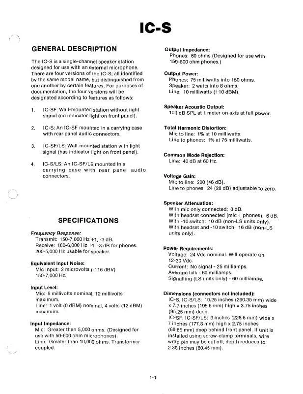
[. . . ] Voltage Gain: Mic t o line: 200 (46 dB). Line to phones: 24 (28 dB) adjustable t o zero. Speaker Attenuation: With mic only connected: 0 dB. With headset connected (mic phones): 6 dB. [. . . ] IC-SF, IC-SFILS: Miclheadset - one XLR-4M. Line - three combination screw-clamp, wirewrap terminals (screw-clamps will accept No. External power -three combination screwclamp, wire-wrap terminals (use optional).
3.
Remove the jumper between the +24 and PH terminals. Connect the +24 terminal.
4.
"+" lead of the supply to the
-
5.
Connect the "-" lead of the supply to the COM terminal.
When all connections are completed, mount unit in electrical box using the four screws supplied.
INSTALLATION
IC-S and IC-SILS
OPERATION
SpeakerlHeadphone VOLUME Control: Adjusts listen level only. SPEAKER Switch (IC-S, IC-SF): This is a threeposition switch. In the ON position, the speaker has normal volume output. In the -10 dB position, speaker output is reduced. In the OFF position, there is no speaker output. The - 10 dB and OFF positions do not affect the headphone or microphone levels. SPEAKER ONIOFF and CALL Switch (IC-SILS, IC-SFILS): This is a three-position switch. The ON and OFF positions turn the speaker on and off but do not affect the headphone output or microphone level when using a headset. The CALL position is used for light signalling. In the CALL position, with the switch held continuously, an inaudible signal is sent to all other stations on the line. On those stations with light signalling the Call Indicator lights will illuminate. When another station responds verbally, release the switch and it will automatically return to the ON position for two-way voice communication. MicIHeadset Connector: Accepts a push-to-talk microphone or a headset with dynamic microphone and headphones. Call Indicator Light (IC-SILS, IC-SFILS): Provides a visual indication when the station is being called.
These stations may be connected to the intercom line using prefabricated cables with XLR-3 end connectors, or cables may be made to lengths as required and terminated with XLR-3 cable connectors.
IC-SF and IC-SFILS
When powering from the intercom line:
1.
Refer to the label on the rear cover Connect the two intercom line wires to the LlNE terminals. Connect the dc return wire t o the SHLD terminal. Connect a jumper between the 4-24 and PH terminals (disregard this step with factoryfresh units - jumper should already be in place).
2.
3.
4.
When powering from a separate dc supply:
1. 2.
Refer to the label on the rear cover. Connect the two intercom line wires to the LlNE terminals.
1
1
SPEAKER SWITCH SPEAKER/HEADPHONE VOLUME CONTROL
SPEAKER ON/OFF AND CALL SWITCH
I r'
SPEAKER/HEADPHONE VOLUME CONTROL
1
MICROPHONEIHEADSET CONNECTOR
I
4 C A L L INDICATOR LIGHT CONNECTOR
[----IMICROPHONE/ HEADSET
IC-SILS, IC-SFILS FRONT PANEL
IC-S, IC-SF FRONT PANEL
IC-S, IC-SILS REAR PANEL IC-S Reference Guide
MAINTENANCE
IC-S Mechanical Exploded View
1-4
IC-S Mechanical Parts List
All parts used on all versions unless otherwise specified * ITEM NO. 1 2 3 4 5 6 7 8 9 10 11 12 13 14 15 16 17 18 19 20 21 22 23 24 25 26 27 28 29 30 31 32 33 34 35 36 37 38 39 40 DESCRIPTION Cover, End (IC-S, IC-S/LS) Screw, 6-32 x 3/4 (IC-S, IC-S/LS) Nut, Hex, No. [. . . ] All capacitors in microfarads unless otherwise noted.
REFERENCE NO. C1, 2, 3 C4 C5, 7, 9 C6 C8 C10 C11 CRI J5 Q1, 3 Q2 R1 R2, 5 R3, 15 R4 R6 R7 R8 R11 R12 R14 U1 VRI DESCRIPTION Capacitor, Ceramic, 0. 001, 50V, +lOO/o Capacitor, Ceramic, 100 pF, 500V, +1O0/0 Capacitor, Tantalum, 0. 1, 35V, +20°/0 Capacitor NPO, Ceramic, 0. 0022, 50V, +2% Capacitor, Electrolytic, 4. 7, 25V, +20°/0 Capacitor, Electrolytic, 10, 25V, +20°/o Capacitor, Ceramic, 0. 047, 25V, f 80 -20% Diode, 1N4148 Connector, 7-Position Transistor, 2N2925 Transistor, J175 Resistor, 2. 2M Resistor, 1M Resistor, 20K Resistor, 10K Resistor, 62K Resistor, 10K Resistor, 47K Resistor, 24K, %W, k2% Resistor, Variable, 5K, %W, +1O0/0 Resistor, 1. 2K, %WI +5% IC, Tone Decoder, XR567 Diode, Zener, 6. 2V, %W, +5% Socket, &Pin PART NO. 52676-101 52157-008 52257-065 35694-034 52723-013 52723-014 52158-033 52228-000 57721-007 51547-000 54687-001 52154-201 52154-209 52154-250 52154-257 52154-238 52154-257 52154-241 52155-248 57 148-048 52154-456 53258-000 51302-017 53041-002
JUMP FEMO COM
NOTES: 1. ALL RESISTORS IN OHMS, 1/4 WATT, 25% UNLESS R 5 , : OTHERWISE NOTED. [. . . ]


