Detailed instructions for use are in the User's Guide.
[. . . ] SVM-01007
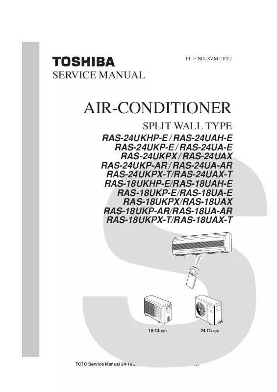
SERVICE MANUAL
AIR-CONDITIONER
SPLIT WALL TYPE
RAS-24UKHP-E / RAS-24UAH-E RAS-24UKP-E / RAS-24UA-E RAS-24UKPX / RAS-24UAX RAS-24UKP-AR / RAS-24UA-AR RAS-24UKPX-T/RAS-24UAX-T RAS-18UKHP-E/RAS-18UAH-E RAS-18UKP-E/RAS-18UA-E RAS-18UKPX/RAS-18UAX RAS-18UKP-AR/RAS-18UA-AR RAS-18UKPX-T/RAS-18UAX-T
18 Class
24 Class
TCTC Service Manual 24/18UKHP-E (EN) File No. SPECIFICATIONS
1-1 RAS-24UKHP-E/24UAH-E, RAS-24UKP-E/24UA-E RAS-24UKPX/24UAX, RAS-24UKP-AR/24UA-AR RAS-24UKPX-T/24UAX-T 1-2 RAS-18UKHP-E/18UAH-E, RAS-18UKP-E/18UA-E RAS-18UKPX/18UAX, RAS-18UKP-AR/18UA-AR RAS-18UKPX-T/18UAX-T
2. CONSTRUCTION VIEWS
2-1 Indoor Unit (RAS-24UKHP-E, 24UKP-E, 24UKPX, 24UKP-AR, 24UKPX-T) 2-2 Indoor Unit (RAS-18UKHP-E, 18UKP-E, 18UKPX, 18UKP-AR, 18UKPX-T) 2-3 Outdoor Unit (RAS-24UAH-E, 24UA-E, 24UAX, 24UA-AR, 24UAX-T) 2-4 Outdoor Unit (RAS-18UAH-E, 18UA-E, 18UAX, 18UA-AR, 18UAX-T)
3. WIRING DIAGRAM
3-1 RAS-24UKHP-E/RAS-24UAH-E 3-2 RAS-24UKP-E/RAS-24UA-E RAS-24UKPX/RAS-24UAX RAS-24UKP-AR/RAS-24UA-AR RAS-24UKPX-T/RAS-24UAX-T 3-3 RAS-18UKHP-E/RAS-18UAH-E 3-4 RAS-18UKP-E/RAS-18UA-E RAS-18UKPX/RAS-18UAX RAS-18UKP-AR/RAS-18UA-AR RAS-18UKPX-T/RAS-18UAX-T
4. [. . . ] Incorrect Cable Connection between Indoor and Outdoor Units
Follow the details of 9-2. The indoor unit is connected to the outdoor unit with 4 If there is no trouble corresponding to 9-2, check whether cables. Check that the indoor and outdoor units have been or not there are faulty parts following 9-4. Selfproperly connected with terminals assigned the same Diagnosis by Remote Control. If the connectors are not properly connected, the outdoor unit will not operate normally, or 9-2. Basic Check Items OPERATION lamp and TIMER lamp will blink (5Hz). Program Control The line voltage must be AC 220 240V. If it is not within The microcomputer operates as shown in Table 9-2-1 to this rage, the air conditioner may not operate normally. If there are any operational problems, check whether or not the problems correspond to Table 9-2-1. If they correspond to the Table, they are not problems with the air conditioner, but they are indispensable operations to control and maintain the air conditioner properly. 1 Operation of Air Conditioner Descriptions
2 3 4 5
6 7 8
9 10 11
When the main power supply is turned The OPERATION lamp blinks to indicate that power is turned on, the OPERATION lamp on the indoor on. If the [START/STOP] button is pressed, the lamp stops blinking. The lamp also blinks when the power supply is turned unit blinks. The indoor fan motor speed does not The indoor fan motor speed is automatically controlled in the Dry operation. The compressor is not turned off even The compressor has a function that it is not turned off for 3 though the room temperature is in the minutes after it is turned on even though the room range that the compressor is turned off. temperature is in the range that the compressor is turned off. The compressor is not turned on and off In the Dry operation, the compressor is turned on and off even though the thermo control is automatically at the regular intervals, independent of the thermo control. lamp is indicated during the Defrosting Heating operation starts. operation or if the indoor heat exchanger temperature is low when the Heating operation starts. At this time, the indoor fan motor stops to prevent cold air from blowing in the room. The outdoor fan motor stops in the When the indoor heat exchanger temperature is high, the outdoor fan motor is stopped by the high-temperature limit Heating operation. The compressor is not turned on even The compressor is not turned on in the restart delay timer (3though the room temperature is in the minutes timer) operation. [. . . ] 21 22 23 24 25 26 27 28 29 30 31 32 33 41 42
Part No.
Description
43T00024 Panel, Air Outlet 43T00025 Panel, Front 43T00026 Panel, Side 43T42002 Base Assembly 43T19012 Guard, Fin 43T19011 Guard, Fan 43T91001 Plate, Roof 43T42005 Plate, Valve, Packed 43T15001 Handle 43T43318 Condenser Assembly 43T46014 Valve, Packed 15. 88 43T46016 Valve, Packed 6. 35 43T47310 Bonnet, 15. 88 Dia. 43T60035 Terminal Block, 4P 43T60036 Terminal Block, 3P, 30A 43T60037 Filter, Clamp 43141301 Compressor, PH280X3-4MS 43T62014 Protector, Cord
43T62015 Protector, Cord 43T49011 Base, Spring A 43T49019 Spring, Buffer 43T49012 Base, Spring B 43T21013 Motor, Fan, AC220 240V 50Hz 43T21014 Motor, Fan, AC220 240V 50Hz 43T20010 Fan, Propeller, 490 43T96001 Bushing 43T96004 Bushing, Cord 43T62013 Cover, E-Parts 43T52301 Switch, Magnet, CLK-35J 43T55021 Capacitor, 45MFD, 420V 43T55014 Capacitor, 3. 5MFD, 450V 43T96003 Clip, Cable 43T33002 Spark Killer 43T47309 Tube, Capillary, 0. 8 Dia.
* Motor Fan 43T21014 use with model RAS-24UA-AR only
75
TCTC Service Manual 24/18UKHP-E (EN) File No. SVM-01007
11-6 Outdoor Unit RAS-18UAH-E
7 14 28 29 32 40 41 10 1 35 30 31 12 39 25 26 27 4 11 34 15
13 2
37, 38
16, 17
5 18, 19 3
9
24 8 6
20: Capillary tube 0. 8 Dia. 01 02 03 04 05 06 07 08 09 10 11 12 13 14 15 16 17 18 19 20 21 Part No. [. . . ]


